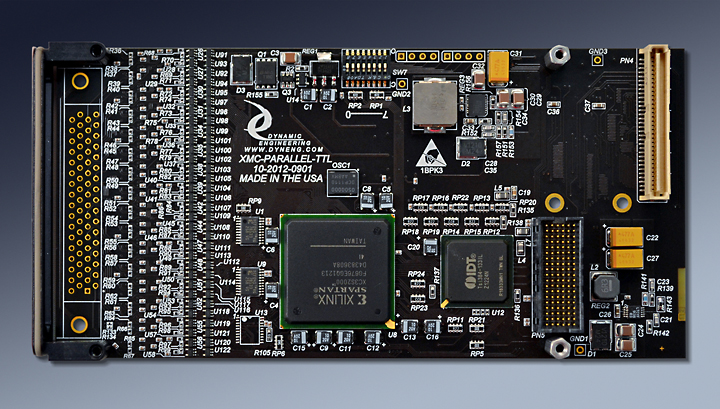
XMC-Parallel-TTL
64 TTL IO in one slot with COS interrupts


Does your system require single ended TTL or CMOS level signals? Dynamic Engineering has a multitude of solutions covering different architectures and mezzanine types. XMC-Parallel-TTL is based on the popular PMC-Parallel-TTL design. The IO definitions are the same to allow ease of migration from PMC to XMC when the time comes. XMC-Parallel-TTL retains Pn4 and Bezel IO options. The bus interface is a 4 lane PCIe implementation using the XMC connector as seen in the photo above. The FPGA is a Spartan III. The FPGA can be redefined to provide state-machines and other IO controllers for specific applications. We ported the "BA16" design to this board with a simple recompile to create the first implementation. XMC-Parallel-TTL is in use testing our XMC carriers using DMA and the IO connections.

XMC compatible XMC-Parallel-TTL has 64 independent digital IO. The high density makes efficient use of precious XMC slot resources. The IO is available for system connection both through the front panel and via the rear [Pn4] connector. A high density 68 pin SCSI III front panel connector provides the front panel IO. The rear panel IO has a PIM and PIM Carrier available for rear panel wiring options. The HDEterm68 can be used as a breakout for the front or rear panel IO. The HDEcabl68 provides a convenient cable. The pin definitions are consistent with the PMC Parallel IO card to enable users of the PMC Parallel IO to migrate to the XMC Parallel TTL quickly and easily.

Each IO is independently programmable. The outputs can be enabled and driven high or low. When disabled on-board pull-ups terminate the lines. The pull-ups can be referenced to 5V or 3.3V with software. A master enable is available to allow the user to synchronize the upper and lower outputs for coherant 64 bit operation in a 32 bit system. The master enable can be set to allow independent upper and lower bank updates. The transmitters are ´125 buffers and the receivers are Schmidt triggered to provide hysterisis. The IO are isolated from the connectors to allow connector selection without creating "stubs". The isolation is in the form of 0402 packaged resistors. Typlically 0 ohms to the rear connector and 22 ohms to the front. Other values can be used. Similarly the pull-ups are individual packages and can be changed from the 470 ohm standard.

All channels can be read as inputs regardless of the transmit enable programming. Local loop-back can be used for BIT. All IO channels can be used as interrupt generators. Interrupts are programmable to be based on either or both edges for "Change of State" operation. An external clock, PCI clock, or oscillator can be selected for the reference on the COS operation. The reference can be programmed to be divided to create lower frequencies. A PLL is available to support user frequency selection to provide the right sampling rate for your application.

VPWR is used to create 5V using a buck-boost DC:DC converter. The Buck-Boost converter design allows XMC-Parallel-TTL to operate with VPWR defined to be 12V or 5V without user intervention. VPWR is monitored and LED´s indicate which power level is supplied. The LED´s are on the rear of the card for easy viewing.

LED´s indicate which PCIe lanes are in use. XMC-Parallel-TTL can operate with 1, 2, or 4 lanes.

The FPGA is loaded from FLASH allowing for field updates and custom designs. You can order based on a similar design and update to the exact design later allowing for a quick start. There are 3 FLASH devices to allow for '2000 or '4000 size FPGA´s to be installed.

Additional features include a user switch [8 positions] ,and PLL with 4 inputs to the FPGA, and local oscillator. The reference to the PLL is sourced by the FPGA allowing for many references and programmed frequencies. A local oscillator is provided. A high quality industrial temperature 25 PPM device is installed with 50 MHz or a design specific frequency. The driver and reference software include utilities to load and reload the PLL with user specific frequency selections. The switch can be used to identify which XMC is being communicated with when more than one are installed in a system or for whatever options [SW or FPGA] are designed.

All of the IO are routed through the FPGA device to allow for custom applications that require hardware intervention or specific timing. For example the design of the PMC Parallel TTL supports internal FIFO´s and DMA. With an added state-machine for your interface the hardware can provide much more than a simple parallel interface. Contact Dynamic Engineering for convenient customer specific implementations.

The base model has a simple to use register based interface. The registers are mapped as 32 bit words. All registers are read-writeable. The Windows® compatible [Win7 or XP] driver is available to provide the system level interface for this design. Use standard C/C++ to control your hardware or use the Hardware manual to make your own software interface. The hardware manual is downloadable from the bottom of this page. The software manual is also available on-line.

Install into a PC with PCIe8LXMCX1 or PCIe8LXMCX2.

64 IO with COS in one slot

XMC-Parallel-TTL Features

  • Size
  • Single wide XMC.

  • Parallel Interface
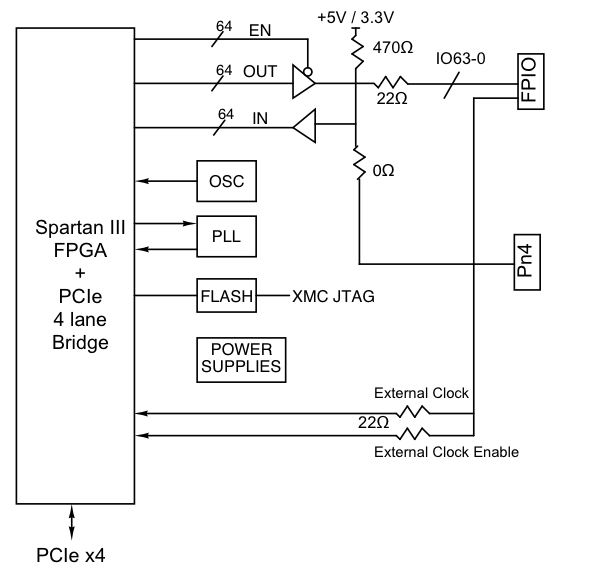
  • 64 independent channels. The pull-ups can be referenced to 3.3V or 5V. Front Panel [Bezel], Rear IO [Pn4] or Both ports available. Unused ports isolated with resistors for "zero bus stub". Matched IO within 1/1000 inch for on-board traces to front and rear.

  • Pull-up Resistor
  • 470 standard, 1K, 4.7K available.

  • Sink Current
  • 64+ mA per channel

  • Cable interface
  • Industry standard SCSI III front panel IO and Pn4 backplane connection.

  • Software Interface
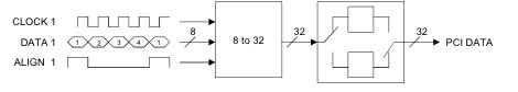
  • 32 bit registers mapped to the 64 IO channels. Read-back of channel control registers and input registers. Read-write of control registers for card configuration.

  • Interrupts
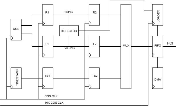
  • All IO Channels can be programmed to cause interrupts. Each channel is programmable to be masked, rising, falling, both [COS].

  • Power Requirement
  • XMC standard. VPWR can be +5 or +12V.

  • Protection
  • The isolation resistors standard is 0 ohms to Pn4 and 22 ohms to Bezel. Resistive coupling for current limiting and ESD protection.

  • COS Clock
  • Input registers are programmable to capture data with the COS clk. SW can select 33 MHz, external or Oscillator as the source for clock. A programmable divider [12 bit] allows a wide range of sampling frequencies to be selected. Some versions use the PLL for the COS clock definition.

  • Custom
  • All bits are routed through the FPGA to allow for custom state-machine implementations. FIFO and Dual Port RAM can be implemented. See custom models below.


    XMC-Parallel-TTL Benefits

  • Speed
  • XMC-Parallel-TTL is a software controlled HW interface. As fast as the PCIe interface can push the data across, the outputs can change. With the Windows® driver several accesses per microsecond can be achieved. Your time to market will be shortened by the easy to use interface, flexibility in design, and off-the-shelf availability. With DMA enabled and FIFO´s instantiated even faster transfers can occur.

  • Price
  • XMC-Parallel-TTL has an attractive price, and low integration cost for a low system cost. XMC Parallel TTL has an associated PIM and PIM Carrier which can lead to further savings in cPCI environments.

  • Ease of Use
  • XMC-Parallel-TTL is easy to use. A point and shoot user interface to the IO. Please download the manual and see for yourself. The engineering kit provides a good starting point for a new user. 64 bits of user defined IO.

  • Availability
  • XMC-Parallel-TTL is a popular board. We keep XMC-Parallel-TTL in stock. Send in your order and in most cases have your hardware the next day - delivered to you via FedEx. Custom versions can be dialed in quickly as well as customer requested VHDL features. Consider using scheduling on your next order. Available now.

  • Size
  • XMC-Parallel-TTL is a standard single wide XMC [single slot] board which conforms to the XMC mechanical and electrical specifications. Eliminate mechanical interference issues.

  • XMC Compatibility
  • XMC-Parallel-TTL is XMC compliant per the VITA specification.

  • PCIe Compatibility
  • XMC-Parallel-TTL is PCIe compliant. You can develop with a PCIe to XMC adapter - PCIe8LXMCX1 or PCIe8lXMCX2 etc..


    Engineering Kits
    Dynamic Engineering provides Engineering Kits to help our customers have a successful and quick integration. Engineering Kits will save time and money with decreased T&I. We recognize that different customers have different needs. The Engineering Kits are standardized in description to help with selection. The kits are segmented to allow for customers who only need hardware support, software support or a mixture. The Engineering Kit is highly recommended for first time buyers. The kit pricing is discounted to encourage their use.

    XMC-Parallel-TTL-ENG .......... Hardware Support Engineering Kit includes:
    Board level Schematics [PDF], cable and breakout [HDEterm68-MP, HDEcabl68].

    XMC-Parallel-TTL Drivers..........Drivers Included with purchase Windows®XP/2000 and Win7 compliant driver for the XMC-Parallel-TTL:
    Please see the Driver manual for the specifics of installing and using the driver. The driver includes a user application reference which we use to test the boards. The user reference software, driver, and include files make it easy to integrate the XMC-Parallel-TTL into your system.


    Ordering Information
    XMC-Parallel-TTL
    Primary Options:
    Add one: -FP or "blank" for front panel IO[Bezel] , -RP for rear panel IO [Pn4], or -FRP for both

    Secondary Options:
    -CC to add conformal coating
    -ET to add Industrial Temp [-40 +85]
    -TS to add thumbscrew option - standard is latch block
    -3V There is no -3V option for this design as software has control over the reference voltage.


    Items shown with PMC-Parallel-TTL description can be ported rapidly to the XMC-Parallel-TTL. Items shown with an XMC designation have already been ported or designed for the XMC-Parallel-TTL originally.

    Manual - Standard
    Download the
    PMC-Parallel-TTL Rev A1 Manual in Adobe Acrobat PDF format.
    Download the XMC-Parallel-TTL Rev 3p1 Manual

    Customized Hardware
    BA16 has the standard features of the PMC-Parallel-TTL plus:
    Two synchronous parallel ports - 8 bits with reference clock and strobe.
    DMA support with 4Kx32 FIFO on RX, and 2Kx32 FIFO on TX.
    Driver has utilities for programming the PLL using the "JED" file.

    Download the
    PMC-Parallel-TTL-BA16 Hardware Manual in PDF format.
    Download the PMC-Parallel-TTL-BA16 Windows® XP Manual for BA16 version in PDF format.
    Download the PMC-Parallel-TTL-BA16 Windows® 7 Manual for BA16 version in PDF format.
    *The Linux manual is embedded in Linux source files for this project.


    BA17 has the standard features of the PMC-Parallel-TTL plus:
    DMA support for the COS function on the upper 32 bits with 12K x 32 FIFO.
    Programmable [PLL] COS sample rate.
    Driver has utilities for programming the PLL using the "JED" file.

    Download the PMC-Parallel-TTL-BA17 Hardware Manual in PDF format.
    Download the PMC-Parallel-TTL-BA17 Windows® Manual for BA17 version in PDF format.


    Related Products
    HDEcabl68 SCSI II/III Cable
    HDEterm68 SCSI II/III to 68 pin terminal block
    PCIe8LXMCX1 PCIe adapter/carrier card for XMC
    PCIe8LXMCX2 PCIe adapter/carrier card for XMC with 2 positions
    PIM-Parallel-IO facilitate rear panel IO


    Try before you buy program


    Custom, IP, PMC, XMC, PCIe, PCI, PCI-104, PCIe104, cPCI, VPX, VME Hardware, Software designed to your requirements


    Home | News | Search the Dynamic Engineering Site