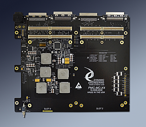
PMC-MC-X4
PMC Carrier with 4 positions

Shown with optional Power Expansion connector installed. See below for RIO model photos.


PMC-MC-X4-RIO is recommended for new implementations. PMC-MC-X4 will remain in production to support previously integrated projects.

The PMC-MC-X4 adapter/carrier converter card provides the ability to install up to 4 (four) PMC cards into a small enclosure. PMC-MC-X4 has two PMC card slots mounted top and bottom to create a compact arrangement with 4 PMC slots. X4 is a complete solution with built in power supplies, thermal protection, voltage monitoring, bus arbitration, clock distribution and more.

Based on 12V or 14-40V "28V" inputs the carrier provides power supplies for the +5, +3.3, +12, and minus 12. A "Power Din 4" connector is used for power input to the X4. With the chassis version, a wall mount transformer supply is provided. The 28V supply is used to make 12V. The 12V is supplied to the PMC´s and the other supplies to generate the 3.3, 5 and -12V. The 3.3 and 5V supplies can source 10A. The -12 is a 4A supply. The power supplies are tied to an optional header to allow other co-located assets to use the X4 generated power. For example when mounting an X4, prPMC, control interface, and laser or other device controlled by the installed PMC´s. With the 12V option the 28V power supply components are not installed and a strap is used to tie the input power [12V] to the 12V plane. In this configuration the 12V will match the input power rail definition. In this version "12V ONLY" is visible in the top side silk screen.

PCI VIO is programmable allowing 5V or 3.3V PMC´s to be used. The voltage select pins are not installed [the keying holes are provided] on the PMC-MC-X4. Many PMC´s are "universal" and can work with 3.3 or 5V PCI backplanes. The DIPSWITCH selects 5V or 3V operation. The Silk-Screen has a legend with the DIP switch selection options.

The PCI bus is suitable for 32 and 64 bit operation at 33 or 66 MHz. Alternate clock frequencies can be supported by special request. Each of the slots including Slot 0 has a request and grant connection to the arbiter located within the CPLD. The CPLD also provides a selectable 66/33 MHz reference clock routed to each of the slots. The reference clock is buffered with a "zero delay" buffer and matched length routed to each of the PMC slots. Interrupts are routed from Slots 1, 2, and 3 to slot 0. IDSEL is selectable to be in the lower or upper address range via the DIPSWITCH. Reset is based on supervisor circuits checking that the 3.3V and 5V rails are valid or the reset option from the DIPSWITCH. Slots 0,1,2 and 3 are clearly marked in the silk-screen.

PrPMC´s frequently have concentrated power consumption requiring air flow for proper cooling. The larger load also puts a thermal load on the PMC-MC-X4 components. The X4 has been designed with convection cooling in mind. The slots in the side of the PMC MC X4 design are for fans. [Please refer to the pictures above.] The PMC-MC-X4 has switched power [+5V, 1.5A] for fans plus an available override for always on [DIPSWITCH]. The prPMC can control the fans with a pin on the Pn4 IO connector. If your prPMC does not have a temperature sensor or control feature the always on mode can be selected.

The PMC-MC-X4 Chassis comes with twin fans making use of the cutouts. The X4 chassis comes with cutouts on the opposite side to provide for proper air flow across the PMC´s and PMC-MC-X4. A similar configuration is recommended when using the PMC-MC-X4 with an alternate chassis. Please refer to the picture of the open X2 chassis toward the bottom of the PMC-MC-X4-Chassis page.

If you need to interconnect the PMC´s without using the PCI bus for higher bandwith or specialized signaling the X4 has a selection matrix to interconnect the Pn4 connectors on slots 1, 2, and 3 as required. The connections are designed for high speed use with reference planes, proper trace and space matched length routing. Suitable for high and low speed signals as well as differential pairs.

A new feature available with revision B FLASH, for revision F and later boards is the ability operate in Standard or Remote mode. Using the DIPSWITCH(5) select the Remote mode to receive a clock from an external source and to use an external second level of arbitration. A net of 3 PMC positions are available in this configuration as position 0 is used for the cable between the host system and the X4 acting as an expansion chassis. Initial testing was performed with an Extendio II . PMC-BiSerial-BA16´s were used to run DMA tests on multiple positions in parallel plus do standard target IO accesses. If you have the right HW but the previous FLASH please contact Dynamic Engineering for an update.

If you have custom requirements please call or e-mail us with the details.

Dynamic Data Sheets have current features described, the following may help to see which features you have with an older board.
Revision History:
Rev A - Original, 12V only power supply
Rev B - Add fuse protection and misc. clean-up
Rev C - Add Power Supply sequencing
Rev D - Add 28V power supply option and Pn4 interconnect bus
Rev E - Increase current to 10A on 3.3 and 5V rails, add user power [out] connector,
convert from shunts to DIPSWITCH options, switch to Power DIN 4 connector,
remove exposed gold at board edge, widen slightly to provide complete mounting holes on RHS.
Rev F - Add voltage monitor curcuits to check over and under voltage conditions.
Add second 5V power supply for fan operation
Add thermal switch to shut-down main power supply when over limit [75C - std, programmable]
Add Vertical input power option
Rev G - Manufacturability update
Rev H - Add RIO option, convert to wider input range power supply designs, increase current to 15A on 5, 3.3V rails, add fan speed control.


PMC-MC-X4 Features

  • Size
  • Custom. Slightly larger than 2 PMC´s side by side.

  • PMC Positions
  • 4 PMC Slots provided.

  • Clocks
  • PCI bus can operate at 66 or 33 MHz. The PMC must be 66 MHz capable for 66 MHz operation to work properly. User switch to allow or disable 66 MHz. operation. Automatic selection with PMC control via M66EN

  • Access Width
  • Standard PCI byte lanes supported for byte, word and long access dependent on installed PMC. 64 or 32 bit operation supported.

  • Software Interface
  • PMC register definitions as defined by installed hardware. No software set-up required by PMC-MC-X4.

  • Interrupts
  • INTA, B, C, D routed to Slot 0 connector from PMC´s. Standard interrupt routing, Request/Grant and IDSEL rotation between the slots. Slot 0 is to be populated with a PrPMC.

  • Arbitration
  • Requests and Grants routed to CPLD provided on X4. All slots can be bus masters.

  • Signal Conditioning
  • PCI signals are routed and terminated IAW the PCI specification.

  • Power
  • Internal Power Supplies for std model: +5(10A), +3.3(10A), +12(4A), -12V(4A) VIO supplied to PMC slots. Reference rail can be 12V or "28V" 14-40 is the range for the 28V power. 18-36 is recommended to provide margin and increase efficiency.

    Internal Power Supplies for -RIO model: +5(15A), +3.3(15A), +12(4A), -12V(4A) VIO supplied to PMC slots. Reference rail range 10-40V.

  • Power Sharing Option
  • Optional connector can be installed in place of PMC 3 [standard model - on card edge for RIO model] to provide 28V, 12V, -12V, 5V, 3.3V and ground to another piece of equipment. Mainly useful when installed in a chassis in common with other equipment which requires an external DC supply. Please note that the current used on this connector competes with the current available to the PMC´s.

  • Pn4 Interconnect
  • Pn4 for Slots 1,2,3 can be interconnected on the standard model - not available on RIO model. Signals are pre-routed with matched length differential pairs suitable for single ended or differential operation. Zero ohm reisistor packs are used to make or leave open the connections between the different slots. There are 4 signals per resistor pack - two pairs. Select which packs are installed to create buses between the 3 PMC´s with any 2 or all three connected for each rpack position.

  • VIO
  • VIO is programmable by the user. 3.3V or 5V selected with DIPSWITCH. Please note the VIO current is part of the 3.3V or 5V power budget [depending on selection made].

  • Thermal
  • PMC-MC-X4 is a low power design with minimal heat dissipation of its own. Most PMC´s will require forced air cooling. For the standard model: Switched 5V power is available for fans along with cut-outs on the side of the X4 to support closely mounted fans with little mechanical overhead. 1.5A total available between the two positions. Routed to allow full load on either position. Option for PMC control over FAN switch or DIPSWITCH control. The fan power [revision E and later] comes from a separate 5V supply. An on-board thernal switch is set to 75C and has 10C hystersis to shut off the main supply in the case of being over temperature. The fan power will continue to operate when the main power is down.

    For RIO model the FAN power is 12V and comes from a speed control device where fan speed is controlled via temperature. The over temperature control system is retained. 12 V is not disabled by the overtemperature control.

  • IO Interface
  • Front Bezel IO supported. RIO model supports both Bezel and Pn4 IO from all positions. Pn4 IO is routed with matched length, impedance controlled, differential traces between each Pn4 and matching VHDCI connector.

  • LED´s
  • +3V, +5V, +12V, -12V and "PMC Present".

  • JTAG
  • JTAG header is available to interconnect with PMC inslot 0. JTAG pin definitions are in the silkscreen.


    PMC-MC-X4 Benefits

  • Speed
  • Direct connect non-bridge based design for optimum PCI performance. 66/33 MHz and 64/32 capable to work in your system.

  • Price
  • Make use of existing PMC designs in applications demanding high density without paying for the expense of a new design and layout. Quantity discounts are available.

  • Warranty
  • 1 year warranty. Extended warranty available.

  • Ease of Use
  • PMC-MC-X4 is easy to use. User options on a single DIPSWITCH. No software required to operate the X4.

  • Availability
  • PMC-MC-X4 is a stocked item. Send in your order and in most cases have your hardware the next day.

  • Size
  • PMC-MC-X4 is a custom board. Please see manual for dimensions.

  • PMC Compatibility
  • The PMC-MC-X4 is PMC compliant per the IEEE 1386 specification. All Dynamic Engineering PMC Modules are compatible with the PMC-MC-X4.


    PMC-MC-X4 Ordering Options
    PMC-MC-X4: Standard PMC-MC-X4 with 28V power supply (see below for -RIO models)
    -12V Standard board with 28V power supply removed and strapped for 12V operation
    -EXT24 Add external power supply to provide 24V reference for X4 operation. Use with "28V" internal power supply
    -EXT12 Add external power supply to provide 12V reference for X4 operation. Use with "12V" internal power supply
    -XX Standard board with added user defined Pn4 inter-connection bus. See table at end of manual
    -VPI Change to 2 pin Molex Vertical Power Input connector instead of PowerDin4
    -PE Add right angle Power Expansion connector located at the bezel end of PMC Position 3
    -VPE Add Vertical Power Expansion connector located at the bezel end of PMC Position 3
    -FPR Move Fan headers to rear of X4
    -NPS Remove Power Switch for "Always on" operation

    Client Options - Short cuts to multiple selections: Use one of these if they match your requirements or request a new bundle for yours.
    -CY4 28V version of X4 plus -VPI, -FPR, -NPS
    -CY5 28V version of X4 plus -VPE, -VPI, -FPR, -NPS


    Quantity

    Front and Rear views of RIO model X4 Motherboard.

    PMC-MC_X4-RIO is recommended for new implementations. PMC-MC-X4 will remain in production to support previously integrated projects.

    Manual
    You must have Adobe Acrobat to read our PDF files.

    Download the
    PMC-MC-X4 Manual in PDF format


    Custom, IP, PMC, XMC, PCIe, PCI, cPCI, PC104p, PCIe104, VME, VPX Hardware, Software designed to your requirements


    Home | News | Search the Dynamic Engineering Site