Made in USA
The Embedded Solutions Experts
PCIe4lHOTLinkx5
PCIe design with up to 5 HOTLink ports. PECL or LVDS IO types.


PCIe4lHOTLinkx5 Description
- Windows® or Linux driver included with purchase
- PCIe 4 lanes interface with up to 5 HOTLink full duplex ports
- PECL or LVDS IO interface
- PLL and Oscillator for frequency selection
- Programmable start of Frame sequence, Programmable End of Frame Sequence
- Programmable multi-channel synchronization, interframe delay
- 1 year warranty standard. Extended warranty available.
- Extended Temperature standard.
- ROHS and Standard processing available
HOTLink is used in applications demanding high speed and high reliability including sonar, radar, other scanning applications, seismic, oil exploration etc. Alternate purposes would include high speed buses between equipment or within equipment for command and control, data transfer etc. For example the first client project featuring PCIe4lHOTLinkx5 uses the HOTLink interface to capture data from high speed A/D´s.
PCIe4lHOTLinkx5 is a PCI Express card with 5 HOTLink receiver/transmitter pairs. Each of the HOTLink channels is supported with a separate DMA transfer engine plus local memory. All ports are full duplex with the lower 4 connected through a VHDCI connector and port 5 connected though coax connectors [4]. The standard version has many triggering / transfer control programmable features to allow start of frame sequences, end of frame sequences, synchronized start across channels, constant [programmed] delay between frames [indepedent each channel].
The HOTLink protocol implemented provides positive emitter coupled logic (PECL) or LVDS data inputs and outputs. The transmit byte rate is determined by the programmed frequency of the PLL clock output. This clock is multiplied ten times by the HOTLink transmitter to send the transmit byte data stream which is expanded to 10 bits by the internal 8B/10B encoder. The PLL is programmed via software over a serial I2C interface.
Up to five independent HOTLink channels are provided per card. The base design implemetation has programmable frame definitions - which K´s are used to start a frame and end a frame. The start and stop are further programmable to be up to 3 K´s in series with the same or different values for each. Interrupt options are provided to support frame capture nad movement to the host memory.
The x5 design is related to the x6 with the main difference being the connectors used, and organization of the ports. Designs on either board can be ported between them.
PCIe4lHOTLinkx5 utilizes a Spartan 6 100 FPGA. The FPGA allows for a lot of internal memory and complex data manipulation in HW. The memory is typically used for FIFO´s or RAM. The FIFO´s can be accessed by single-word [target] read/writes as well as DMA burst transfers. A FIFO test bit in each channel control register enables the data to be routed from the transmit to the receive FIFO for a full 32-bit path providing loop-back testing of the FIFO´s. The channels are supported with 12 independent DMA engines. A local arbitration unit keeps everything moving efficiently. DMA transfers can be programmed for any size transfer from very small to multiple megabytes using the scatter gather capable programming model.
All parts are industrial temp or better [-40C <=> +85C]. Conformal coating, is available to help adapt to your environment.
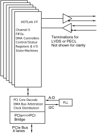
PCIe4lHOTLinkx5 Block Diagram
PCIe4lHOTLinkx5 is a PCI Express card with 5 HOTLink receiver/transmitter pairs. Each of the HOTLink channels is supported with a separate DMA transfer engine plus local memory. All ports are full duplex with the lower 4 connected through a VHDCI connector and port 5 connected though coax connectors [4]. The standard version has many triggering / transfer control programmable features to allow start of frame sequences, end of frame sequences, synchronized start across channels, constant [programmed] delay between frames [indepedent each channel].
The HOTLink protocol implemented provides positive emitter coupled logic (PECL) or LVDS data inputs and outputs. The transmit byte rate is determined by the programmed frequency of the PLL clock output. This clock is multiplied ten times by the HOTLink transmitter to send the transmit byte data stream which is expanded to 10 bits by the internal 8B/10B encoder. The PLL is programmed via software over a serial I2C interface.
Up to five independent HOTLink channels are provided per card. The base design implemetation has programmable frame definitions - which K´s are used to start a frame and end a frame. The start and stop are further programmable to be up to 3 K´s in series with the same or different values for each. Interrupt options are provided to support frame capture nad movement to the host memory.
The x5 design is related to the x6 with the main difference being the connectors used, and organization of the ports. Designs on either board can be ported between them.
PCIe4lHOTLinkx5 utilizes a Spartan 6 100 FPGA. The FPGA allows for a lot of internal memory and complex data manipulation in HW. The memory is typically used for FIFO´s or RAM. The FIFO´s can be accessed by single-word [target] read/writes as well as DMA burst transfers. A FIFO test bit in each channel control register enables the data to be routed from the transmit to the receive FIFO for a full 32-bit path providing loop-back testing of the FIFO´s. The channels are supported with 12 independent DMA engines. A local arbitration unit keeps everything moving efficiently. DMA transfers can be programmed for any size transfer from very small to multiple megabytes using the scatter gather capable programming model.
All parts are industrial temp or better [-40C <=> +85C]. Conformal coating, is available to help adapt to your environment.
PCIe4lHOTLinkx5 Block Diagram
PCIe4lHOTLinkx5 Features
Size
1/2 length PCIe.
HOTLink Interface
5 independent Bidirectional PECL/LVDS based HOTLink channels. Impedance controlled differentially routed channels.
Cable interface
VHDCI and Coax connectors at the PCIe bezel. 4 full duplex on VHDCI and 1 full duplex via Coax. Fiber Interface signals on VHDCI connector for lower 4 ports. Custom cables are available.
Software Interface
Channelized design with repeating common offsets for registers in each channel. DMA and direct access to FIFO´s attached to HOTLink IO. Drivers available for Windows®, option for Linux and VxWorks. Detailed hardware / memory map information in HW manual [download at the bottom of this page] for user designed drivers. Reference software using the Dynamic Drivers is provided with the driver. Existing Dynamic Engineering drivers are free to Dynamic Engineering HOTLink clients.
Interrupts
The HOTLink board supports various interrupts. All interrupts are individually mask´able and a channel master interrupt enable is provided to disable all interrupts on a channel simultaneously. The current real-time status is also available making it possible to operate in a polled mode.
Power Requirement
+12, +3.3 from PCIe connector.
Custom
All bits are routed through the FPGA to allow for custom state-machine implementations. FIFO and Dual Port RAM can be implemented. See custom models below.
Statement of Volatility
Download PDF here - for ccPMC version but similar for this card.
Reliability
TBD hours. Bellcore. GB 25c
PCIe4lHOTLinkx5 Benefits
Speed
Your time to market will be shortened by the easy to use interface, flexibility in design, and off-the-shelf availability. PCIe4lHOTLinkx5 is a software controlled HW interface. With DMA enabled and FIFO´s instantiated fast transfers can occur. Each channel has a separate DMA controller to allow for high speed large transfers without SW intervention required.
Price
PCIe4lHOTLinkx5 has an attractive price, and low integration cost for a low system cost. PCIe4lHOTLinkx5 can be used with Ethernet cables or custom cables for your system. Please contact Dynamic Engineering about your IO requirements.
Ease of Use
PCIe4lHOTLinkx5 is easy to use. A point and shoot user interface to the IO. Please download the manual and see for yourself. The engineering kit provides a good starting point for a new user. The drivers [Windows® or Linux] come with reference software demonstrating DMA, register and memory accesses, PLL programming utilities and loop-back tests. The reference software is in source form and can be used for your design.
Availability
PCIe4lHOTLinkx5 is designed to be customized. The base version is available from stock. New
clientizedversions can be dialed in quickly. We can ship a model that is
just like but differentto you right away and follow-up with new FLASH files to match your requirements. You can make a quick start having the HW available right away and adding features as they are available. The base model is highly programmable and will work in many cases.
PCIe Compatibility
PCIe4lHOTLinkx5 is PCIe compliant. You can develop in a PC.
Part Number: PCIe4lHOTLinkx5
Ordering Options
- PCIe4lHOTLinkx5 Standard board - with PECL IO , Industrial temperature components 5 channels
- -LVDS Switch to LVDS IO
- -ROHS Use ROHS processing. Standard processing is ""leaded"
- -CC Option to add Conformal Coating
- -1 Port 0 only
- -2 Port 0-1 only
- -3 Port 0-2 only
- -4 Port 0-3 only
- -5 All channels populated [0-5]default
- -SMB SMB port only with all memory allocated to this port.
PCIe4lHOTLinkx5 Drivers
Software Support for PCIe4lHOTLinkx5 includes: Windows® drivers
Please see the Driver manuals for the specifics of each type.
Drivers and Reference SW are developed for each type / version of PCIe4lHOTLinkx5 implemented. When custom versions are ordered the NRE will include providing Windows, Linux packages. For off-the-shelf models, select on the Manuals tab, the Windows® and Linux SW shown is included with your purchase of the HW. Unsupported SW versions may have an NRE requirement.
Integration support is available. Please contact Dynamic Engineering for this option or download the Technical Support Description from the Company button.
PCIe4lHOTLinkx5 Manuals
RV1 Hardware Design Manual Main product manual with Address and Biitmap information, example use, pinouts, specifications and more.
Windows Driver Manual for RV1 design Installation and use of the Windows Driver and reference SW
Generalized HOTLink interface design with many programmable features for start and stop sequences, type of data to capture, type of transmission, special encodings, programmable data rates etc. This is a single port design using the SMB connectors. The memory is reallocated to the single port. Separate SW package for this model.
SMB Hardware Design Manual Main product manual with Address and Biitmap information, example use, pinouts, specifications and more.
SMB Windows 10 SW Manual Installation and overview of API. Use with Driver and UserAp package. UserAp has examples of transmitting, receiving, internal and external tests. etc.