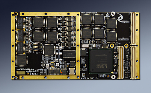
ccPMC-HOTLINK
Conduction Cooled PMC Format
Shown with Transformer option
Six Channel HOTLink Interface


HOTLink is used in applications demanding high speed and high reliability including sonar, radar, other scanning applications, seismic, oil exploration etc. Alternate purposes would include high speed buses between equipment or within equipment for command and control, data transfer etc. ccPMC-HOTLink is a conduction cooled PMC card with 6 HOTLink receiver/transmitter pairs plus 12 differential IO. Each of the HOTLink channels is supported with a separate DMA transfer engine plus local memory.

The HOTLink protocol implemented provides positive emitter coupled logic (PECL) data inputs and outputs. The receive side can be direct or transformer coupled. The transmit byte rate is determined by the programmed frequency of the PLL clock A output. This clock is multiplied ten times by the HOTLink transmitter to send the transmit byte data stream which is expanded to 10 bits by the internal 8B/10B encoder. The PLL is programmed via software over a serial I2C interface.

Up to six independent HOTLink channels are provided per card. Each HOTLink channel has four differential I/O signal pairs: A HOTLink differential PECL output, a HOTLink differential PECL input and two bi-directional differential RS-485 lines. The RS-485 IO each have independent direction and termination controls to allow programmable operation with many IO requirements. The 485 IO can be used for an alternate purpose and is directly controlled by the FPGA

The initial design implementation with revision 1 was for a client using the RS-485 as the request control path and HOTLink as the return data path. The initial rev 2 design is a single channel Image capture interface with a transmit channel for test purposes. Alternate configurations are easily implemented. For example the RS-485 can be replaced with LVDS IO or a mixture of the two. VHDL changes can be made to use the IO in an alternate method. Please contact Dynamic Engineering with your requirments.

The HOTLink input is can be transformer-coupled into a dual 50Ω terminations referenced to 1.8 volts. The signals are then AC-coupled into the HOTLink receiver inputs referenced to 3.5 volt. The HOTLink output is AC-coupled after the bias/termination network. Both AC coupling stages can be replaced for a DC coupled system.

ccPMC-HOTLink has been updated to utilize a Spartan 6 100. The larger faster FPGA allows for a lot of internal memory and more complex data manipulation in HW. The memory is typically used for FIFO´s or RAM. The FIFO´s can be accessed by single-word [target] read/writes as well as DMA burst transfers. A FIFO test bit in each channel control register enables the data to be routed from the transmit to the receive FIFO for a full 32-bit path for loop-back testing of the FIFO´s. The channels are supported with 12 independent DMA engines. A local arbitration unit keeps everything moving efficiently. DMA transfers can be programmed for any size transfer from very small to multiple megabytes using the scatter gather capable programming model.

This PMC module is conduction-cooled and has no front panel connector. All I/O connections are routed through PN4 and the PMC carrier to the outside world. All parts are industrial temp or better [-40C <=> +85C]. Conformal coating, thermal gluing and thermal foam are available options help adapt to your environment.


ccPMC-HOTLink Block Diagram

ccPMC-HOTLink Features

  • Size
  • Single wide ccPMC.

  • HOTLink Interface
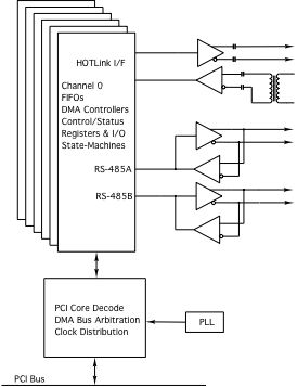
  • 6 independent Bidirectional PECL based HOTLink channels. Impedance controlled differentially routed channels.

  • RS485/LVDS Interface
  • 6 pairs of RS485/LVDS IO can be allocated 2 per HOTLink channel or used as a separate function with 12 available. 40/200 MHz IO, matched length, differentially routed with controlled impedance. Programmable terminations and options for tristate [pull-up/pulldown] control.

  • Cable interface
  • Pn4 backplane connection. Your PMC carrier will specify the system connector.

  • Software Interface
  • Channelized design with repeating common offsets for registers in each channel. DMA and direct access to FIFO´s attached to HOTLink IO. Drivers available for Windows® , with options for Linux, VxWorks or detailed hardware / memory map information in HW manual [download at the bottom of this page] for user designed drivers. Reference software using the Dynamic Drivers is available.

  • Interrupts
  • The HOTLink board supports various interrupts. All interrupts are individually mask´able and a channel master interrupt enable is provided to disable all interrupts on a channel simultaneously. The current real-time status is also available making it possible to operate in a polled mode.

  • Power Requirement
  • +3V, +5V

  • Custom
  • All bits are routed through the FPGA to allow for custom state-machine implementations. FIFO and Dual Port RAM can be implemented. See custom models below.

  • Statement of Volatility
  • Download PDF here


    ccPMC-HOTLink Benefits

  • Speed
  • Your time to market will be shortened by the easy to use interface, flexibility in design, and off-the-shelf availability. ccPMC-HOTLink is a software controlled HW interface. With DMA enabled and FIFO´s instantiated fast transfers can occur. Each channel has a separate DMA controller to allow for high speed large transfers without SW intervention required.

  • Price
  • ccPMC-HOTLink has an attractive price, and low integration cost for a low system cost. ccPMC-HOTLink can be used with PIM Universal and PIM Carrier in cPCI environments. An integrated rear IO transition solution with your specific connector requirements can be designed for you. Please contact Dynamic Engineering about your IO requirements.

  • Ease of Use
  • ccPMC-HOTLink is easy to use. A point and shoot user interface to the IO. Please download the manual and see for yourself. The engineering kit provides a good starting point for a new user. The drivers [Windows® or Linux] come with reference software demonstrating DMA, register and memory accesses, PLL programming utilities and loop-back tests. The reference software is in source form and can be used for your design. Modify away.

  • Availability
  • ccPMC-HOTLink is designed to be customized. The base version is available from stock. New clientized versions can be dialed in quickly. We can ship a model that is just like but different to you right away and follow-up with new FLASH files to match your requirements. You can make a quick start having the HW available right away and adding features as they are available.

  • Size
  • ccPMC-HOTLink is a standard single wide ccPMC [single slot] board which conforms to the ccPMC mechanical and electrical specifications. Eliminate mechanical interference issues.

  • PMC Compatibility
  • ccPMC-HOTLink is PMC compliant per the IEEE 1386 specification. ccPMC-HOTLink is also compliant with the conduction cooled PMC specification.

  • PCI Compatibility
  • ccPMC-HOTLink is PCI compliant. You can develop with a PCIe to PMC adapter - PCIeBPMCX1 or 2 position PMC Mini Carrier etc..


    Engineering Kits
    Dynamic Engineering provides Engineering Kits to help our clients have a successful integration. Engineering Kits save time and money with decreased T&I.
  • We recognize that different customers have different needs. Choose your own components.
  • Software options are listed below. Existing driver/userap package are available at no charge to our HOTLink clients.
  • We will be happy to design for your new requirement. Our NRE costs are competitive.
  • Dynamic Engineering offers design support to help you with your integration. Several pre-configured plans are available or we can create one specifically for you.
  • In addition Dynamic Engineering designs and manufactures cables, carriers [to adapt into a PC or other platform], and other "glue" that you need to make your system go.


  • ccPMC-HOTLink Reference Software
    Please see the corresponding Driver manual for the specifics of installing and using the driver. The driver includes a user application reference which we use to test the boards. The user reference software, driver, and include files make it easy to integrate the ccPMC-HOTLink into your system. Please
    contact Dynamic Engineering if you would like us to produce one for your PMC or a third party design.


    Ordering Information
    Base part number: ccPMC-HOTLink-
    -CC to add conformal coating
    -ROHS to add ROHS processing


    Manuals - Standard
    You must have Adobe Acrbat to read PDF files
    Rev 02 and later projects
    Description: AP1 is a single channel receive oriented Image capture design. 64Kx32 FIFO´s for receive and transmit. K chars are used to pad with nulls, provide a synchronization pattern to initiate frame capture and to provide the interframe gap. A PLL with SW interface provides frequency programability. Options for interrupt and polled operation with individual masks to allow for a variety of operational concepts. Windows® 7 driver and UserAp available.
    Download the
    ccPMC-HOTLink AP1 Rev C Hardware Manual

    Kaon1: TTL and HOTLink interfaces with command / response type interaction. 2 Ports per ccPMC-HOTLink-KAON1. Windows® and Linux [debian] support.
    Download the ccPMC-HOTLink KAON1 HW Manual
    Download the ccPMC-HOTLink KAON1 Linux Manual
    Download the ccPMC-HOTLink KAON1 Windows 7 Manual
    Download the ccPMC-HOTLink KAON1 Windows 10 Manual

    Rev 01 projects- Spartan III based implementation
    Description: The rev 1 design HOTLink receiver is supported by a 4k by 32-bit input data FIFO and the HOTLink transmitter has a 2k by 32-bit output data FIFO. These FIFO´s can be accessed by single-word read/writes as well as DMA burst transfers. A FIFO test bit in each channel control register enables the data to be routed from the transmit to the receive FIFO for a full 32-bit path for loop-back testing of the FIFO´s. Data is latched and the bus immediately released on a write-cycle. As soon as data is present in the FIFO it is pre-read to be immediately available for a read cycle. This allows minimal delay on the PCI write to transmit FIFO path and PCI read from the receive FIFO path as well as the accesses for the transmit and receive state machines.

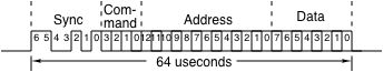
    Base Transmit Request Timing

    Each channel also has two bi-directional RS-485 lines running an asynchronous 32-bit msb first protocol with low marking state. The 16x receive clock is supplied by the PLL clock A output. Each line is supported by a 1k by 32-bit FIFO that can be configured for either input or output use. Either line can be configured as a general purpose input or output, or setup to send data access requests at regular intervals (variable from 1.5 msec to about 3.5 msec in 2 usec increments) using a pre-defined 7-bit sync pattern. These requests trigger the output of a block of data that is received by the HOTLink receiver. The RS-485 FIFO´s are only accessed using single-word transfers. Each FIFO can be directly written and read for FIFO testing or normal operation as either a receiver or transmitter.

    Each channel also has two bi-directional RS-485 lines running an asynchronous 32-bit msb first protocol with low marking state. The 16x receive clock is supplied by the PLL clock A output. Each line is supported by a 1k by 32-bit FIFO that can be configured for either input or output use. Either line can be configured as a general purpose input or output, or setup to send data access requests at regular intervals (variable from 1.5 msec to about 3.5 msec in 2 usec increments) using a pre-defined 7-bit sync pattern. These requests trigger the output of a block of data that is received by the HOTLink receiver. The RS-485 FIFO´s are only accessed using single-word transfers. Each FIFO can be directly written and read for FIFO testing or normal operation as either a receiver or transmitter. Download the ccPMC-HOTLink Rev A Hardware Manual
    Download the ccPMC-HOTLink Rev A Windows® Driver Manual
    Download the ccPMC-HOTLink Rev A Linux Driver Manual


    Related Products
    HDEcabl68 SCSI II/III Cable
    HDEterm68 SCSI II/III to 68 pin terminal block
    PCIBPMCX1 PCI adapter card with differential controlled impedance connectivity from Pn4
    PCIeBPMCX1 PCI Express to PMC adapter card with differential controlled impedance connectivity from Pn4
    PIM-Universal facilitate rear panel IO


    Custom, IP, PMC, XMC, PCIe, PCI, VPX, VME Hardware, Software designed to your requirements


    Home | News | Search the Dynamic Engineering Site