Made in USA
The Embedded Solutions Experts
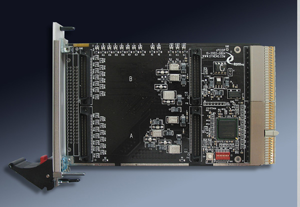
cPCI2IP
cPCI adapter for 2 IP Modules. 8, 16, 32 bit accesses supported

cPCI2IP Description
- Windows® , Linux driver included with purchase
- 32 bit PCI operation ↣ can be installed in any cPCI position.
- 2 IndustryPack Module positions w/ 8⇆32 MHz. operation
- Fused, FIltered 5V, +12V, -12V supplied to IPs
- Multi-word accesses supported including 32, 16, 8 bit
- Full memory space supplied to each position
- 3U 4HP
- Industrial Temperature standard
- Ribbon Cable or blank bezel depending on model
- 1 year warranty standard. Extended warranty available.
- ROHS and Standard processing available
If you want to use IndustryPack® modules with your cPCI system then cPCI2IP is the choice for you. cPCI2IP combines features you need with simplicity and speed. 2 IP modules can be installed. 32 bit and double wide modules fit right in. Each position has independent operation - control, clocking, IO, power filtering and protection. cPCI2IP is highly integrated with the PCI and IP interfaces closely coupled within the same FPGA. As a result cPCI2IP is faster, has a higher MTBF, and is easier to use than competing designs. There are fewer initialization steps and fewer PCI addresses to deal with and yet there are more features to work with. With the Windows or Linux drivers operation can be "plug and play". cPCI2IP is a mature design currently revision 05 on the PCB. A planned upgrade to Spartan VI is in the works - software transparent - to provide added lifespan to this product. Dynamic Engineering launched cPCI2IP in 2002 and still supports today. Our base drivers are written to support both PCIe and PCI based IP carrriers allowing our IP drivers to be common for both bus types. This means an IP driver developed for cPCI2IP will work with PCI3IP, PCIe3IP, PCIe5IP, cPCI2IP, cPCI4IP, VPX2IP, PC104pIP etc. For newer platforms requiring PCIe please consider PCIe3IP and PCIe5IP designs.
Multi-board operation is supported. With multiple cPCI2IPs in your system and unique cabling, sensors etc. for each slot on each cPCI2IP it is important to "know" which cPCI2IP is which and to properly control the IP modules mounted to them. A surface mount "dip switch" is provided to create a programmable identifier to the software. A specific cPCI2IP can be matched up with the PCI address allocated to make for deterministic control. The switch can also be used for other purposes; configuration control or debugging for example. The switch values are available to be read via the PCI bus. The Dynamic Drivers make use of the Switch and Slot information to uniquely identify each installed IP and to associate a system "handle" with a particular module.
Each slot has a separate clock controller for 8 and 32 MHz operation. The clocks are locked together for the slots plus the state-machine. Glitch free operation means the frequency can be be changed on the fly. Series and parallel terminations with equal length traces insure clean clocks and coherant operation across the IPs and the controlling state-machine. Clock distribution is critical for reliable operation.
Each position has resettable "self healing" fused filtered power. +5, +12, and -12V supported.
Industry standard 50 pin [ribbon cable] headers are used with the IO connectors. The connectors are "wired" 1:1 from the IP IO connector to the Header connector. The Headers are numbered with standard ribbon cable conventions. The traces are matched length between the IO connector and header for each channel. Bezel and Rear IO options are isolated with 0 ohm resistors mounted back to back for "Zero" stub length. HDRterm50 can be used to create a terminal block interface. Both bezel connectors come with ejectors. The front panel is supplied with a blank bezel or the ribbon cutout version depending on the ordering option. Bezel IO models come with the "Condo Header" cutout and Rear IO models -J2 come with a blank bezel.
Slots A/B are configured to accept two single IPs, or a double wide Industrypack compatible design. The data bus is designed to allow for 32 bit IP Bus operation. The data bus width is controlled by the address range the slot is controlled with. Automatic switching makes it possible to switch data bus size without changing the control registers for seamless operation.
The IPs can be reset from the control register within the FPGA via the software interface. The IPs are reset on power-up via a supervisory circuit that guarantees the 200 mS minimum reset requirement in the IP specification. The resets only affects the IP slots. In addition IP-Debug-Bus can be used and has a separate reset button only affecting the position it is installed onto.
LEDs are provided to each of the IP slots for activity indicators. When each slot is accessed the LED is flashed. The FPGA provides a "one shot" circuit to stretch the "on" time to make it visible. Power indicator LEDs [3] are provided. An additional eight user LEDs are available for debugging or other purposes.
IndustryPacks are usually 16 bit devices and the PCI bus supports 32 bits. cPCI2IP accepts 32 bit PCI accesses and converts them into two 16 bit accesses with an auto-incremented or static address. One PCI access can be used to write to or read from two IP locations or twice to one location. Byte, Word and Long Word accesses are supported to the 16 and 32 bit IP sites from the PCI bus. If a 32 bit IP has been installed then direct 32 bit operation can be utilized.
The IP accesses are protected by a watch-dog timer. The timer is started at the beginning of each IP access. If the timer expires before the IP being accessed responds, a bus error internal to the cPCI2IP is created. The cPCI2IP responds normally to the host, not tying up the PCI bus, and provides status and an optional interrupt to alert the host to the problem with the IP. The Bus Error timer is useful in situations where the software may want to cause a bus error to find out what is installed or where a hung system would have consequences. Multi-threaded software operation is supported with separate bus error status in each of the slot control registers.
The PCI bus is defined as little endian and many IPs have their register sets defined to operate efficiently with a little endian interface. The default settings on the cPCI2IP are "straight through" byte for byte and D15-0 written to address 0x00 before D31-D16 written to address 0x02 when long words are written to 16 bit ports. Please note that any long word address can be used. The lower data is written to the lower address first, then the upper data to the upper address. Each slot has a ByteSwap and WordSwap control bit to allow Byte and Word Swapping to be performed to accommodate alternate IP and OS requirements.

Byte Swapping accesses to a 16 bit port.

Byte Swapping access to a 32 bit port
The cPCI2IP is a universal board design and can be used in any cPCI slot. The cPCI2IP is not keyed to allow installation into 3.3 or 5V cPCI defined slots.
Connector positioning is compatible with IP-Debug-Bus to allow the user to isolate and debug the control interface of an IP. The IP-Debug-IO can be used in conjunction with the cPCI2IP and IP-Debug-Bus to provide test-points on the IO signals and loop-back capability for the IP.
Multi-board operation is supported. With multiple cPCI2IPs in your system and unique cabling, sensors etc. for each slot on each cPCI2IP it is important to "know" which cPCI2IP is which and to properly control the IP modules mounted to them. A surface mount "dip switch" is provided to create a programmable identifier to the software. A specific cPCI2IP can be matched up with the PCI address allocated to make for deterministic control. The switch can also be used for other purposes; configuration control or debugging for example. The switch values are available to be read via the PCI bus. The Dynamic Drivers make use of the Switch and Slot information to uniquely identify each installed IP and to associate a system "handle" with a particular module.
Each slot has a separate clock controller for 8 and 32 MHz operation. The clocks are locked together for the slots plus the state-machine. Glitch free operation means the frequency can be be changed on the fly. Series and parallel terminations with equal length traces insure clean clocks and coherant operation across the IPs and the controlling state-machine. Clock distribution is critical for reliable operation.
Each position has resettable "self healing" fused filtered power. +5, +12, and -12V supported.
Industry standard 50 pin [ribbon cable] headers are used with the IO connectors. The connectors are "wired" 1:1 from the IP IO connector to the Header connector. The Headers are numbered with standard ribbon cable conventions. The traces are matched length between the IO connector and header for each channel. Bezel and Rear IO options are isolated with 0 ohm resistors mounted back to back for "Zero" stub length. HDRterm50 can be used to create a terminal block interface. Both bezel connectors come with ejectors. The front panel is supplied with a blank bezel or the ribbon cutout version depending on the ordering option. Bezel IO models come with the "Condo Header" cutout and Rear IO models -J2 come with a blank bezel.
Slots A/B are configured to accept two single IPs, or a double wide Industrypack compatible design. The data bus is designed to allow for 32 bit IP Bus operation. The data bus width is controlled by the address range the slot is controlled with. Automatic switching makes it possible to switch data bus size without changing the control registers for seamless operation.
The IPs can be reset from the control register within the FPGA via the software interface. The IPs are reset on power-up via a supervisory circuit that guarantees the 200 mS minimum reset requirement in the IP specification. The resets only affects the IP slots. In addition IP-Debug-Bus can be used and has a separate reset button only affecting the position it is installed onto.
LEDs are provided to each of the IP slots for activity indicators. When each slot is accessed the LED is flashed. The FPGA provides a "one shot" circuit to stretch the "on" time to make it visible. Power indicator LEDs [3] are provided. An additional eight user LEDs are available for debugging or other purposes.
IndustryPacks are usually 16 bit devices and the PCI bus supports 32 bits. cPCI2IP accepts 32 bit PCI accesses and converts them into two 16 bit accesses with an auto-incremented or static address. One PCI access can be used to write to or read from two IP locations or twice to one location. Byte, Word and Long Word accesses are supported to the 16 and 32 bit IP sites from the PCI bus. If a 32 bit IP has been installed then direct 32 bit operation can be utilized.
The IP accesses are protected by a watch-dog timer. The timer is started at the beginning of each IP access. If the timer expires before the IP being accessed responds, a bus error internal to the cPCI2IP is created. The cPCI2IP responds normally to the host, not tying up the PCI bus, and provides status and an optional interrupt to alert the host to the problem with the IP. The Bus Error timer is useful in situations where the software may want to cause a bus error to find out what is installed or where a hung system would have consequences. Multi-threaded software operation is supported with separate bus error status in each of the slot control registers.
The PCI bus is defined as little endian and many IPs have their register sets defined to operate efficiently with a little endian interface. The default settings on the cPCI2IP are "straight through" byte for byte and D15-0 written to address 0x00 before D31-D16 written to address 0x02 when long words are written to 16 bit ports. Please note that any long word address can be used. The lower data is written to the lower address first, then the upper data to the upper address. Each slot has a ByteSwap and WordSwap control bit to allow Byte and Word Swapping to be performed to accommodate alternate IP and OS requirements.
Byte Swapping accesses to a 16 bit port.
Byte Swapping access to a 32 bit port
The cPCI2IP is a universal board design and can be used in any cPCI slot. The cPCI2IP is not keyed to allow installation into 3.3 or 5V cPCI defined slots.
Connector positioning is compatible with IP-Debug-Bus to allow the user to isolate and debug the control interface of an IP. The IP-Debug-IO can be used in conjunction with the cPCI2IP and IP-Debug-Bus to provide test-points on the IO signals and loop-back capability for the IP.
cPCI2IP Features
Size
3U 4HP
IP compatible slots
2 independent positions. A/B can be used with 32 bit IP designs.
Clocks
Each position has independent selection of 8 and 32 MHz operation. Clock selection can be changed on-the-fly with glitch free operation.
Access Width
Each position can be accessed as byte, word, or x32. Multiple word accesses can be static or auto-incrementing to the IP slot.
Bus Error
The Watch-Dog timer protects against PCI bus hangs by responding when the IP is not installed or has a failure.
Cable interface
Industry standard 50 pin box header connectors. Right angle through the bezel. Special bezel with cable slot for IO egress through the bezel. Rear [J2] IO also supported
Software Interface
Control registers are read-writeable. IO, ID, MEM, INT spaces supported. Windows® , Linux Drivers available
Interrupts
Each IP has 2 potential interrupts. All are transferred to the PCI bus. Control registers are provided to enable which interrupts are sent to the host and Status registers are provided to determine the source of the interrupt.
Power Requirement
+5V, +12V, -12V current determined by IPs installed. 3.3V used by FPGA. Full IP spec power available to each position.
DIP switch
An 8 position switch is available to allow for configuration control, or to facilitate debugging, and to provide a positive ID of each cPCI2IP in your system
LEDs
+5V, +12V, -12V and activity LEDs. 8 user LEDs also available.
Reliability
1,290,549 Hours Bellcore SR332

Block Diagram of cPCi2IP.
cPCI2IP Benefits
Speed
With the direct PCI to IP Bridge design featured in cPCI2IP the access to your hardware happens faster than in competing designs. The 32 bit access capabilities further extends the lead in speed. Compatible with mult-processor systems without sacrificing access times for single CPU systems. Multiple threads with accesses to different IPs are supported.
Price
System level cost is best when reasonably priced reliable hardware is used and NRE minimized. With cPCI2IP, driver support for the carrier and IP level, reference software, history of reliable operation, and fantastic client support your cost per unit and overall costs are attractive. Please check the current per item pricing with the storefront lower on this page. Orders can be placed via the on-line ordering system or via phone / email PO order systems.
Ease of Use
cPCI2IP is easy to use. A point and shoot user interface to the IP sites. Please download the manuals and see for yourself. Reference software is provided in source form to get you started. The generic IP interface allows the driver to be used with IPs without a driver specific to that design.
Availability
We work to keep cPCI2IP in stock. Dynamic Engineering has in house manufacturing capabilities for short lead times on larger orders.
IP Specification Compatibility
cPCI2IP is IP compliant per the VITA 4 - 1995 specification. All Dynamic Engineering IP Modules are compatible with the cPCI2IP. All other IP Modules which are compliant with the VITA specification can be expected to work. ID, IO, INT, and Memory spaces are supported in all 5 positions.
cPCI Compatibility
cPCI2IP is a PCI compliant device. cPCI2IP can be expected to work in any cPCI compliant backplane. Rear IO modules will need to be installed into backplane positions with RIO supported [not 64 bit PCI]. ESD strip is incorporated into the design. EMC gasket coverage where possible around the bezel connector.
Part Number: cPCI2IP
Ordering Options
- cPCI2IP Standard board - Industrial Temperature components with 2 IP positions Add any of the following build options after the PN as shown below:
- -J2 cPCI2IP standard model with J2 IO only
- -IO cPCI2IP standard model with Bezel and J2 IO
- -CC Option to add Conformal Coating
- -ROHS Use ROHS processing. Standard processing is ""leaded"

cPCI2IP Drivers
Software Support for cPCI2IP includes: includes: Windows® 10 (included), Linux(included), and VxWorks(additional fee) compliant drivers
Please see the Driver manuals for the specifics of each type.
Windows or Linux drivers for cPCI2IP. The drivers are designed to be overlayed with individual IP Module(s) driver(s). IP drivers are auto installed for each instance detected. Please see the Driver manual for the specifics of writing your board interface. Please contact Dynamic Engineering if you would like us to produce one for your IP or a third party design. Our Windows driver comes with IP-Generic which is automatically installed when a specific driver is not found for a particular IP Module. IP-Generic can be used to control your IP including handling interrupts, and accesses to all 4 space types.
Linux
The cPCI2IP Linux driver is a bus driver capable of supporting multiple (up to 64) IndustryPack buses/carrier cards. This driver interfaces with the ipack-core Open Source code to support IndustryPack devices. This Open Source code has been slightly modified, and is included with the tar-ball for this driver.
A generic IPACK driver (ipack_gen) and user library (libipack) has been developed by Dynamic Engineering. This driver and library may be sufficient for developing user space drivers for a device depending upon the complexity of that device. Other device specific user libraries and kernel drivers are available for Dynamic Engineering Industry Pack modules. The diagram below illustrates possible layering of Industry Pack components:

Integration support is available. Please contact Dynamic Engineering for this option or download the Technical Support Description from the Company button.
Please see the Driver manuals for the specifics of each type.
Windows or Linux drivers for cPCI2IP. The drivers are designed to be overlayed with individual IP Module(s) driver(s). IP drivers are auto installed for each instance detected. Please see the Driver manual for the specifics of writing your board interface. Please contact Dynamic Engineering if you would like us to produce one for your IP or a third party design. Our Windows driver comes with IP-Generic which is automatically installed when a specific driver is not found for a particular IP Module. IP-Generic can be used to control your IP including handling interrupts, and accesses to all 4 space types.
Linux
The cPCI2IP Linux driver is a bus driver capable of supporting multiple (up to 64) IndustryPack buses/carrier cards. This driver interfaces with the ipack-core Open Source code to support IndustryPack devices. This Open Source code has been slightly modified, and is included with the tar-ball for this driver.
A generic IPACK driver (ipack_gen) and user library (libipack) has been developed by Dynamic Engineering. This driver and library may be sufficient for developing user space drivers for a device depending upon the complexity of that device. Other device specific user libraries and kernel drivers are available for Dynamic Engineering Industry Pack modules. The diagram below illustrates possible layering of Industry Pack components:
Integration support is available. Please contact Dynamic Engineering for this option or download the Technical Support Description from the Company button.
cPCI2IP Manuals
Click on the link to Download selected manuals in PDF format.
Download the cPCI2IP HW Manual in PDF format.
Download the IP Carrier Windows®10 manual. For PCIe and PCI based carriers
Download the Win10 Generic IP Driver Manual in PDF format.
Download the IP Carrier Windows®7 manual. For PCIe and PCI based carriers
Download the IP Carrier and Module Quick Start guide for Windows®7
Download the Win7 Generic IP Driver Manual in PDF format.
Download the IP Carrier Linux Manual
Download the Linux IP Module Manual