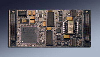
IP-CAN
IP Module with 2 CAN ports. Direct or Isolated
Order This Item
IP-CAN Description
- Windows® driver included with purchase
- 8/32 MHz operation ↣ can be installed in any IP slot.
- Standard Type II module
- 8↔32 MHz. operation
- 2 Ports per IP-CAN
- Programmable terminations for cable terminated or board terminated situations
- Direct Coupled or Isolated ordering options
- 1 year warranty standard. Extended warranty available.
- Extended [Industrial] Temperature standard.
- ROHS and Standard processing available
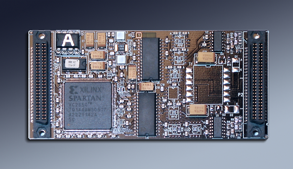
 Shown with Isolation - Power supply and signals
Now you can "talk" to your car and other CAN compatible network devices using IP-CAN. Two channels with Isolation or direct coupled, on board termination or cable based, 8 or 32 MHz IP operation, up to 1 MHz CAN bus operation, and an industry standard CAN bus controller. IP-CAN is currently supported with the Dynamic Engineering Carrier software drivers for Linux and Windows®. Use an existing IP slot within your chassis or combine with a carrier to make PCI-CAN, PCIe-CAN, PC104p-CAN, VPX-CAN or cPCI-CAN.
The IP Module driver can be instantiated multiple times to control multiple cards by the same CPU. IP-CAN when coupled with the Dynamic Driver "knows" what slot it is in and which carrier it is installed into. The slot and carrier information is required when using multiple cards in a PCI/PCIe system with dynamic address assignment. A known system configuration can be combined with the slot and carrier information to deterministically access the right device.
IP-CAN is an IndustryPack Module with two channels of CAN - Controller Area Network. Each CAN channel incorporates the SJA1000 and SJA1041 to provide BasiCAN and PeliCAN operation. Each channel is independent and can be programmed to run at different rates etc. The design utilizes a Xilinx FPGA to provide the IP interface - IDPROM, Bus interface, registers, and control for the CAN controllers [SJA1000]. The CAN interface is done in the memory space using an address bit to distinguish between the two channels. Standard word based offsets are used to memory map the CAN interface into the IP space.
The buses between each of the CAN controllers and FPGA are independent. Completely independent operation the result. The CAN controller is referenced to a 24 MHz. clock. The clock is driven from the FPGA to allow the FPGA to use a rate doubled clock for internal timing synchronization. The conversion from IP to CAN and vice-versa is done with a minimum of delay using the higher reference clock. The number of wait-states utilized is programable based on the IP reference clock. 8 and 32 MHz operation are supported. For maximum efficiency the 32 MHz rate is recommended. All Dynamic Engineering carriers are programmable on a slot-by-slot basis for 8 and 32 MHz operation.

IP-CAN is interconnected to your system with direct or isolated coupling. In the direct mode the CANL and CANH signals are routed to the IP IO connector "directly". A parallel split termination is provided with either the programmed 60.4 ohms per side or 1K ohms per side. With the revision 2 cards, the termination is programmable with software. Select the 1K termination for systems with terminations provided in the cabling or on another board. For home-run wiring or if IP-CAN is the last device the 60.4 ohm termination is recommended.
Isolated connections are accomplished by the use of a separate isolated power supply to provide power to the transceivers [SJA1041] and galvanic coupling on the signals between the transceiver and controller or FPGA. The power supply uses a split transformer to provide independent isolated power for each channel as well as between the board and the system.
The software interface is designed to be consistent and straight-forward. The IP interface provides the board level control with a base register and one channel control register per channel. The transceiver mode, master reset, and interrupt masking are accomplished in the channel control registers. The status register provides the channel interrupt and error status. The base level registers are located in the IO space. The base register provides the IP clock selection [8 or 32 MHz timing] and a software interrupt. The CAN registers are located in the IP Memory space to allow a direct decoding with the standard SJA address definitions. The hardware manual has a complete register map and bit maps for the FPGA registers.
There is ample room within the FPGA to add custom state-machines etc. as your needs require. Please contact Dynamic Engineering with any special requirements.
PCIe implementations can be done with the PCIe3IP and PCIe5IP. Applications from 1 to 10 CAN connections per PCIe slot.
PCI implementations can be done with the PCI3IP and PCI5IP. Applications from 1 to 10 CAN connections per PCI slot.
cPCI 3U is supported with the cPCI2IP. Applications from 1 CAN connection to 4 per 3U cPCI slot.
cPCI 6U is supported with the cPCI4IP. Applications from 1 CAN connection to 8 per 6U cPCI slot.
PC104p is supported with the PC104pIP. Applications with 1 or 2 CAN connections per PC104 stack position.
PC104p situations with a custom mechanical can be done with the PC104p4IP.
Channel counts from 1 CAN connections to 8 per PC104 stack position.
3U VPX is supported with the VPX2IP. Applications from 1 CAN connection to 4 per 3U VPX slot.
6U VPX is supported with the VPX4IP. Applications from 1 CAN connection to 8 per 6U VPX slot.
IP-429 Features
Size
1.8 x 3.9 inches nominal Type II with low profile components on rear
IO
2 independent ports based on SJA1000 and SAJ1041 combination
Clocks/Configuration
Compatible with 8 and 32 MHz IP bus operation. The CAN Controller is completely programmable to provide a variety of speeds [up to 1 MHz], IO types, and modes of operation
IP Decoding
Word, or multiple word payload [x32, x64 etc See PCIe carriers]. ID, IO, INT, MEM spaces supported.
Isolation
Optional Galvanic Isolation with isolated power supply
Software Interface
Control registers are read-writeable
Windows®, reference SW and Drivers
Windows®, reference SW and Drivers
Interrupts
Programmable interrupts for each port are supported. Masked interrupts can be used in polled mode by reading the status register. Interrupts are mapped to INTR0n on IP bus.
Power Requirement
+5V 86 mA typical in direct coupled mode
Volatility
Statement of Volatility
Reliability
TBD million hours. Bellcore. GB 25c
IP-CAN Benefits
Speed
The IP interface supports 32 MHz operation for quick data loading and unloading. The interface supports interrupts and polling. The CAN interface supports the standard rates and can be reprogrammed to alternate user requirements. Dynamic Engineering carriers support 32 to 16 conversion in HW allowing for 32 bit accesses on the host bus. Our new PCIe carriers support x8, x16, x32, and x64 accesses to the IP. Fill or read the buffers with quad accesses for higher performance.
Price
System level cost is best when reasonably priced reliable hardware is used and NRE minimized. With IP-CAN, driver support for the carrier and IP level, reference software, history of reliable operation, and fantastic client support your cost per unit and overall costs are attractive.
Ease of Use
IP-CAN is easy to use. All registers are read-write and word aligned. There is a lot of flexability with interrupt and polled mode operations. The industry standard SJA1000 CAN controller is used to provide a consistent software interface with any previous design work. Please download the manuals and see for yourself. Reference software is provided in source form to get you started. The reference software does multiple tests including loop-back.
Availability
There are 2 basic models with 2 ports of either direct or isolated CAN interface. Stocked in small quantities. Special versions and larger orders may have a delay based on part availability. An advantage of working with Dynamic Engineering is the availability of our own manufacturing capability. Production of larger orders will be faster than you might expect.
IP Specification Compatibility
IP-429 is compliant per the VITA 4 - 1995 specification. Tested with PCI and PCIe based carriers. All Dynamic Engineering IP Modules are compatible with the PCIe3IP, PCIe5IP, VPX2IP, PCI3IP, PCI5IP, cPCI2IP, cPCI4IP, PC104pIP etc. IP-429 will operate with any IP specification compliant carrier board.
Part Number: IP-429
Ordering Options
-
-40 to 85C Standard Temperature range
- IP-CAN................2 CAN Ports with Direct Coupled operation
- IP-CAN-ISO.........2 CAN ports with Isolation
- -CC Option to add Conformal Coating
IP-CAN Drivers
Software Support for IP-CAN includes: Windows® 7
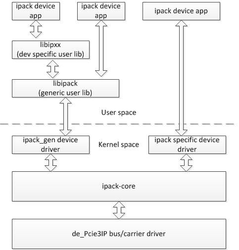
The IP driver is layered and operates on top of the Carrier driver. IP drivers are auto installed for each instance detected. Please see the Driver manuals for the specifics of each type.
The Windows driver works with IP-CAN to provide direct programming in the Pelican or Standard CAN modes. The driver supports switching between modes, controlling both channels on each card, and direct mapping of the cards to the slots for positive cable assignments. The driver has been used for extensive testing with both ISO and Direct connect cards. 6 channels were interconnected with both short [several inch long] and long length cables [approximately 120 ft total length with nodes equally spaced] at the full 1 MHz bandwidth. Multiple carriers were used to support the IP´s. Linux can be used as well using the generic mode of the Linux carrier driver. A module driver is in the works.
The driver uses the carrier ID Switch to distinguish between carriers installed in the same system. The slot location determined with the initial PCI/PCIe enumeration operation is added to the switch information to create a physical location description for the card.
The IP-CAN hardware and driver can be used with any of the Dynamic Engineering IP Carriers. Porting between different form factors is low cost, and easy with software that stays consistent.
Drivers and Reference SW are developed for each type / version of IP-CAN implemented. Windows® is included with your purchase of the HW. A small one-time charge is required for the VxWorks versions. Unsupported SW versions may have an NRE requirement.
Integration support is available. Please contact Dynamic Engineering for this option or download the Technical Support Description from the Company button.

Reference diagam of how our Linux Driver / Application layer operate with the Carrier and IP Module.
The IP driver is layered and operates on top of the Carrier driver. IP drivers are auto installed for each instance detected. Please see the Driver manuals for the specifics of each type.
The Windows driver works with IP-CAN to provide direct programming in the Pelican or Standard CAN modes. The driver supports switching between modes, controlling both channels on each card, and direct mapping of the cards to the slots for positive cable assignments. The driver has been used for extensive testing with both ISO and Direct connect cards. 6 channels were interconnected with both short [several inch long] and long length cables [approximately 120 ft total length with nodes equally spaced] at the full 1 MHz bandwidth. Multiple carriers were used to support the IP´s. Linux can be used as well using the generic mode of the Linux carrier driver. A module driver is in the works.
The driver uses the carrier ID Switch to distinguish between carriers installed in the same system. The slot location determined with the initial PCI/PCIe enumeration operation is added to the switch information to create a physical location description for the card.
The IP-CAN hardware and driver can be used with any of the Dynamic Engineering IP Carriers. Porting between different form factors is low cost, and easy with software that stays consistent.
Drivers and Reference SW are developed for each type / version of IP-CAN implemented. Windows® is included with your purchase of the HW. A small one-time charge is required for the VxWorks versions. Unsupported SW versions may have an NRE requirement.
Integration support is available. Please contact Dynamic Engineering for this option or download the Technical Support Description from the Company button.

Reference diagam of how our Linux Driver / Application layer operate with the Carrier and IP Module.
IP-CAN manuals
Click on the links to Download selected manuals in PDF format.
Download the IP Carrier and Module Quick Start guide for Windows®7
IP Carrier and Module Quick Start guide for Windows®10
IP-CAN Hardware Manual
Win7 driver installation and use manual
IP Carrier Linux Manual
Linux IP Module Manual
VxWorks IP Module Manual
Download the IP Carrier and Module Quick Start guide for Windows®7
IP Carrier and Module Quick Start guide for Windows®10
IP-CAN Hardware Manual
Win7 driver installation and use manual
IP Carrier Linux Manual
Linux IP Module Manual
VxWorks IP Module Manual


