PMC-Serial
Highly flexible Communications Interface
with Synchronous and Asynchronous Serial Protocols
UART and SCC
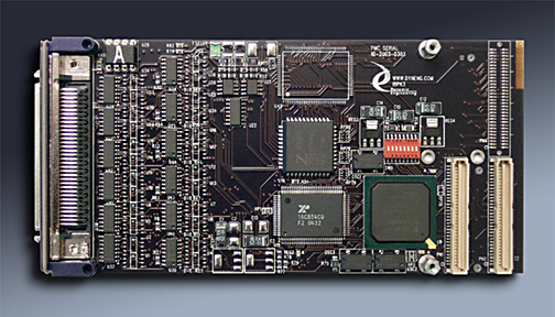
PMC-Serial


Replace several cards with one to save time, cards, slots and stretch your budget.

PMC-Serial is capable of providing multiple serial protocols, both synchronous and asynchronous with a wide range of baud rates. PMC-Serial has up to 8 UART channels, and two SCC channels. The protocol processors are complemented with a variety of IO which can be selected as a build options. RS-232, RS-485, RS-422, and RS-423 are supported. Two enhanced hysteresis MIL STD 188-114A receivers, and two open drain active low output drivers are also provided. The SCC and UART IO are tied to the Xilinx and then to the IO to allow for programmable options and ease of customerization.

Configuration options are built into the board layout, including a second quad UART replacing the SCC and RS-485 I/O. Different oscillators can be installed, or other modifications can be made to accommodate your particular requirements. The new variation will be offered as a "standard" special order product. Please see the bottom of this web page for current versions offered or contact Dynamic Engineering with your custom application.

An EXAR XR16C854 implements the UART interface. This quad UART device is compatible with the industry standard 16550 UART, and is equipped with 128 byte FIFO´s, independent Tx and Rx FIFO counters, automatic hardware/software flow control, and many other enhanced features. The Xilinx design supports the UART´s with a pre-read function and internal memory to allow for pipelined access with lower latency than would otherwise be possible. In addition the character based UART data can be interfaced with wider words.

The synchronous interface uses a Zilog Enhanced Serial Communication Controller, the Z85230. This dual channel, multi-protocol device can implement various bit and byte-oriented synchronous protocols such as HDLC, SDLC, IBM BiSync, and handles asynchronous formats as well.

Up to 24 IO can be installed. The RS-232 and RS-485 can be configured in groups of 4. 4 RS-232 TX, 4 RS-232 RX swapped with 4 RS-485. There are 24 differential RS422/485 transceiver locations that can be configured as either receivers or transmitters, 24 single-ended RS188/232/423 drivers operating at selectable voltage levels, and 24 single-ended receivers capable of up to +/- 25V input range.

There are two enhanced hysteresis (~1.5V) RS423 receivers for handling noisy input signals and two open drain outputs that sink up to 65 mA.

The differential input signals are selectively terminated with switched 100Ω terminations. When the channels are set to RS-485 the analog switch(s) and termination resistor(s) are installed to allow for programmable termination. All single ended lines have series 22Ω resistors for circuit protection.

All configuration registers internal to the Xilinx support read and write operations for software convenience. All addresses are long word aligned including the UART and SCC internal registers even though they only have byte-wide registers. Please see the XR16C854 and Z85230 data sheets and user manuals for more information on register access and functions.

PMC-Serial conforms to the PMC and CMC standards. This guarantees compatibility with multiple PMC Carrier boards. Because the PMC may be mounted on different form factors, while maintaining plug and software compatibility, system prototyping may be done on one PMC Carrier board, with final system implementation on a different one.

Interrupts are supported by PMC-Serial. Each of the UART´s and the SCC has a maskable input to the interrupt generation logic in the Xilinx. There is a master interrupt enable that must be set to gate the interrupt onto the PCI bus. The interrupt status is still available in a status register even when the master interrupt enable is off. This facilitates polled operation of interrupt conditions. The individual interrupt conditions are specified in the internal registers of the UART and SCC.

Three oscillators are installed on the board: 12.288 MHz, 18.432 MHz, and 24.000 MHz. These are connected to the Xilinx to allow software selection of the clock source for the serial chips. The clock input for the UART can be driven by any of the three oscillators or the PCI clock. In addition, the UART C channel has its own clock input, which can be selected independently of the clock for the other three channels. The clock input for the SCC can be driven by the 12.288 MHz or the 18.432 MHz oscillator.

Each of the four UART channels, and the two synchronous serial channels has its own on-board 16-bit baud rate generator to supply a wide range of clock reference frequencies. The SCC can also operate from external clock sources with separate Rx clock input and Tx clock input/output pins for each channel.

While the UART data bus is only eight bits wide, 16-bit and 32-bit accesses for Tx and Rx data can be accomplished by enabling special PMC-Serial features. On a write cycle the data is latched and the bus cycle will terminate immediately. The data is then written into the UART Tx FIFO as a background process. During this time the bus is free for accesses other than the UART or SCC, which will not be available until the writes are complete. The 16-bit and 32-bit read functions are similar, but the bus is not released until the UART reads have completed and the data is enabled onto the bus.

If the background pre-read function is enabled, the RXRDYA-D lines are used to determine when data is available to be read from the Rx FIFO for the respective channel. An eight-byte circular buffer is provided for each channel and when data is available, it is automatically read and stored in this buffer. If more than one channel needs to be serviced simultaneously they will be read in a round-robin pattern as long as data is available and the storage is not full. The data in these buffers is read just like a normal data read, but only one wait state is required for the access. Either one, two, or four bytes will be read in a cycle depending on whether 16-bit or 32-bit data reads are enabled.

If data is requested from the pre-read data store when there is not sufficient data stored to satisfy the request, the bus acknowledge will be held off until the data is present causing the PCI bus to hang. To avoid this, a user programmable watchdog timer is supplied to complete the bus cycle and issue an interrupt if the timer expires. The timer count is programmed by writing a value to the PMC_SER_TIMEOUT register. If this value is zero, the counter never expires; otherwise the value is the number of PCI clocks before the bus cycle is aborted. The data read when the timeout occurs comes from the PMC_SER_TIMEOUT_DATA register and can be set to any value desired.

When RS-422/485 transceivers are utilized with the SCC, the direction is pre-determined in full-duplex mode, and in half-duplex mode the direction of the IO is controlled by the PMC_SER_DIR register. In either mode the switched terminations are controlled by the PMC_SER_TERM register. See the bit definitions in the PMC_SER_BASE control register for the various options for IO connections to the SCC signals.

When RS-232 IO is used with the SCC, the direction of the bits is fixed, the direction and termination registers are not used, and half duplex operation is not possible.

Please refer to the XR16C854 and Z85230 documentation for more information on the operation and capabilities of these devices.

PMC-Serial Features

  • Size
  • Single wide PMC.

  • UART Interface
  • Quad UART - XR854 with 128 byte FIFO's. Locations for 2 devices [8 UARTs], full modem controls on some channels

  • SCC Interface
  • Zilog 85x30 enhanced Serial Communications Controller .

  • IO
  • RS232, RS485, RS423, RS188, tristate buffers available. VHDL programming options and build options provide multiple combinations. Up to 24 differential and up to 48 single ended IO plus AUX In and Out.

  • Cable interface
  • Industry standard SCSI III front panel IO and Pn4 backplane connection. IO is selectable as a build option. Pn4 IO is compatible with the PIM-Parallel IO

  • Software Interface
  • All FPGA registers are read-writeable. UART and SCC registers defined by those devices

  • Interrupts
  • UART and SCC can be programmed independently to cause interrupts. Interrupts are mapped to INTA on PCI bus. Polled and interrupt driven capability.

  • Power Requirement
  • +5V, +12, -12.

  • Protection
  • All IO Channels are protected with limiting resistors.


  • Clock
  • Separate Oscillators for UART and SCC.

  • FPGA Clock
  • Custom state machine can be supported with PCI derived or external oscillator based frequencies.

  • Dip Switch
  • 8 position switch provided for positive identification in PCI systems with multiple PMC-Serial cards. Other user defined purposes. Readable via register.


    PMC-Serial Benefits

  • Speed
  • With the integrated PCI to UART and PCI to SCC Bridge featured in the PMC-Serial standard accesses to your hardware happens faster than in competing designs. Throughput is further enhanced when the UART pre-read and data packing modes are used.

  • Price
  • PMC-Serial can potentially replace 2 or more alternate PMC´s with the combination of UART(s), SCC, custom state-machines and buildable IO features. Save cards, Save slots, Save $.

  • Ease of Use
  • PMC-Serial is easy to use. A point and shoot user interface to the UART´s and SCC. Please download the manual and see for yourself. The engineering kit provides a good starting point for a new user.

  • Availability
  • PMC-Serial is a popular board. We keep the PMC-Serial in stock. Send in your order and we will get it to you promptly. Custom versions can be dialed in quickly as well as customer requested VHDL features.

  • Size
  • PMC-Serial is a standard single wide PMC [single slot] board which conforms to the PMC mechanical and electrical specifications. Eliminate mechanical interference issues.

  • PMC Compatibility
  • PMC-Serial is PMC compliant per the IEEE 1386 specification.

  • PCI Compatibility
  • PMC-Serial is PCI compliant. You can develop with a PCI /PCIe to PMC adapter - PCI2PMC or PCIeBPMCX1.


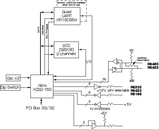
    PMC-Serial Block Diagram
    PMC-Serial block diagram
    Block Diagram for PMC-Serial-L3.
    16 Differential IO for SCC plus RS-232 for UARTs.
    RTN4 version uses RS-232 for all channels.
    Other options are available.


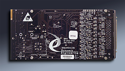
    PMC-Serial Rear view
    Rear View of PMC Serial


    Ordering
    Temporarily under construction...

    Engineering Kits
    Dynamic Engineering provides Engineering Kits to help our customers have a successful and quick integration. Engineering Kits will save time and money with decreased T&I. We recognize that different customers have different needs. The Engineering Kits are standardized in description to help with selection. The kits are segmented to allow for customers who only need hardware support, software support or a mixture. The Engineering Kit is highly recommended for first time buyers. The kit pricing is discounted to encourage their use.

    PMC-Serial-Eng-1 .......... Hardware Support Engineering Kit includes:
    Board level Schematics [PDF], cable and breakout [HDEterm68-MP, HDEcabl68].

    PMC-Serial-Eng-2 .......... Hardware Support plus Driver Engineering Kit includes:
    Board level Schematics [PDF], Software [PMC-Serial Driver and sample application zip file ], cable and breakout [HDEterm68-MP, HDEcabl68]

    PMC-Serial Drivers.......... Software Support Only Windows®XP and 2000 compliant drivers for the PMC-Serial:
    The driver includes a user application reference which we use to test the boards. The user reference software, driver, and include files make it easy to integrate the PMC-Serial into your system. Please note that the driver may need to be customized based on your hardware requirements. Please
    contact Dynamic Engineering if you would like us to produce one for your PMC or a third party design.


    Manuals and Current Versions of PMC-Serial
    Download the
    PMC-Serial -L3 Manual created 9/22/03 in Adobe Acrobat PDF format. RS-232 UART IO, RS-485 SCC IO, plus 2 general purpose high current outputs and 2 hysteresis inputs. Rear panel IO provided [Pn4]

    Download the PMC-Serial-RTN4 Manual created 9/21/04 in Adobe Acrobat PDF format.
    The RTN4 version of the PMC-Serial design has RS-232 for the UART and SCC plus 2 general purpose high current outputs and 2 hysteresis inputs. Front panel IO is provided [P1].

    Download the PMC-Serial-RTN5 Manual updated 1/15/2006 in Adobe Acrobat PDF format.
    The RTN5 version of the PMC-Serial design has 2 - RS-232 and 2 - 422 for the UART, 232 for SCC plus 2 general purpose high current outputs and 2 hysteresis inputs. Front panel IO is provided [P1].

    Download the PMC-Serial-RTN5 Driver Manual Manual updated 1/20/2006 in Adobe Acrobat PDF format.
    Windows® NT Driver for the RTN5 version of the PMC-Serial design.

    Download the PMC-Serial-RTN5 Driver Manual Manual updated 7/18/2008 in Adobe Acrobat PDF format.
    Windows® XP/2000 Driver for the RTN5 version of the PMC-Serial design.

    Download the PMC-Serial-M1 Manual created 4/11/05 in Adobe Acrobat PDF format.
    The M1 version of the PMC-Serial design is a minimized version supplying 4 UART channels each with Rx and Tx in RS-422. Front panel IO is provided [P1]. Pn4 IO is provided


    Related Products
    HDEcabl68 SCSI II/III Cable
    HDEterm68 SCSI II/III to 68 pin terminal block
    PCI2PMC adapter card
    PIM-Parallel-IO facilitate rear panel IO

    Try before you buy program


    Custom, IP, PMC, XMC, PCIe, PCI, VPX, VME Hardware, Software designed to your requirements


    Home | News | Search the Dynamic Engineering Site