IP-Pulse
Five Standard Models with combinations of TTL and differential Pulse Generators
Order This Item
IP-Pulse Description
- 5 combinations of TTL and 485 Pulse Generators available
- Each is independent and can be synchronized
- Plug and Play operation
- Windows Driver available
- 1 year warranty standard. Extended warranty available.
- ROHS and Standard processing available
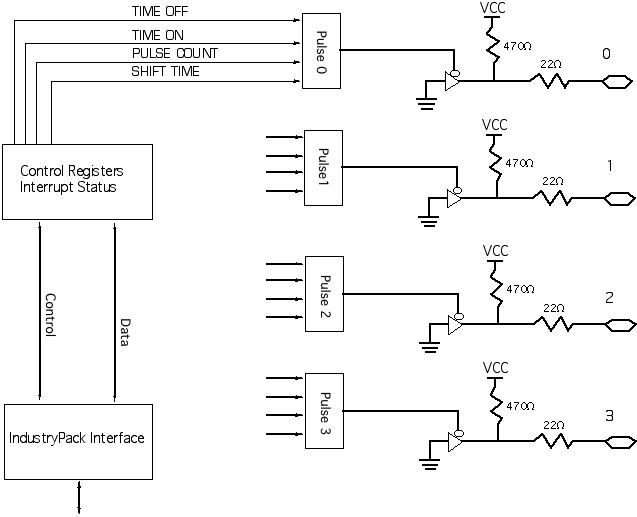
IP-Pulse Block Diagram - TTL/CMOS outputs

IndustryPack® compatible IP-Pulse features 4 independent programmable pulse generators. The outputs can be configured to be TTL /CMOS or RS422/485 compatible in several combinations. A real space saver for systems with both types of IO. Perfect for your embedded control applications. Please download the manual [see bottom of page] for more information. IP-Pulse is available as an add-on IndustryPack Module for use with carriers on all of the common buses: VPX, VMXE, PCIe, PCI, cPCI, and PC104p. IP-Pulse is supported for both Windows® and Linux.
The IP Module driver can be instantiated multiple times to control multiple cards by the same CPU. IP-Pulse when coupled with the Dynamic Driver "knows" what slot it is in and which carrier it is installed into. The slot and carrier information is required when using multiple cards in a PCI/PCIe system with dynamic address assignment. A known system configuration can be combined with the slot and carrier information to deterministically access the right card.
PCI implementations can be done with the PCI3IP and PCI5IP. Applications from 1 to 20 pulse generators per PCI slot.
PCIe implementations can be done with the PCIe3IP and PCIe5IP. Applications from 1 to 20 pulse generators per PCIe position.
cPCI 3U is supported with the cPCI2IP. Applications from 1 to 8 pulse generators per 3U cPCI slot.
cPCI 6U is supported with the cPCI4IP. Applications from 1 to 16 pulse generators per 6U cPCI slot.
PC104p is supported with the PC104pIP. Applications from 1 to 4 pulse generators per PC104 stack position.
PC104p situations with a custom mechanical can be done with the PC104p4IP.
Channel counts from to 16 pulse generators per PC104 stack position.
Each pulse generator is programmable, and has an independent register set [Time ON, Time OFF, Pulse Control, and Shift]. The output waveform is based on a 50 MHz reference. The time between pulses "time off" and the width of each pulse "time on" is controlled with 28 [27-0] bit registers for an effective range of nS to seconds. Each channel can be configured to operate as a free running reference or to output a specific number of pulses. The pulse count has a 24 [23-0] bit register. An additional register contains the SHIFT time which is used to add a phase shift between two or more channels. The registers can be updated on-the-fly to simulate the frequency changes and phase shifts seen in sensors.

Outputs in TTL mode are driven with 32 mA open-drain devices to allow multi-drop applications. 470 ohm pull-up resistors are provided. In 485 mode individual transceivers configured as drivers are utilized. The RS485 devices are rated at 40+ MHz.
Interrupts are supported. When a programmed count completes a programmable interrupt can be generated. When a pulse is output an interrupt can be generated. The channels have individual controls. The status register provides the channels which are causing the interrupt request. The status is held until explicitly cleared by the software.

IndustryPack® compatible IP-Pulse features 4 independent programmable pulse generators. The outputs can be configured to be TTL /CMOS or RS422/485 compatible in several combinations. A real space saver for systems with both types of IO. Perfect for your embedded control applications. Please download the manual [see bottom of page] for more information. IP-Pulse is available as an add-on IndustryPack Module for use with carriers on all of the common buses: VPX, VMXE, PCIe, PCI, cPCI, and PC104p. IP-Pulse is supported for both Windows® and Linux.
The IP Module driver can be instantiated multiple times to control multiple cards by the same CPU. IP-Pulse when coupled with the Dynamic Driver "knows" what slot it is in and which carrier it is installed into. The slot and carrier information is required when using multiple cards in a PCI/PCIe system with dynamic address assignment. A known system configuration can be combined with the slot and carrier information to deterministically access the right card.
PCI implementations can be done with the PCI3IP and PCI5IP. Applications from 1 to 20 pulse generators per PCI slot.
PCIe implementations can be done with the PCIe3IP and PCIe5IP. Applications from 1 to 20 pulse generators per PCIe position.
cPCI 3U is supported with the cPCI2IP. Applications from 1 to 8 pulse generators per 3U cPCI slot.
cPCI 6U is supported with the cPCI4IP. Applications from 1 to 16 pulse generators per 6U cPCI slot.
PC104p is supported with the PC104pIP. Applications from 1 to 4 pulse generators per PC104 stack position.
PC104p situations with a custom mechanical can be done with the PC104p4IP.
Channel counts from to 16 pulse generators per PC104 stack position.
Each pulse generator is programmable, and has an independent register set [Time ON, Time OFF, Pulse Control, and Shift]. The output waveform is based on a 50 MHz reference. The time between pulses "time off" and the width of each pulse "time on" is controlled with 28 [27-0] bit registers for an effective range of nS to seconds. Each channel can be configured to operate as a free running reference or to output a specific number of pulses. The pulse count has a 24 [23-0] bit register. An additional register contains the SHIFT time which is used to add a phase shift between two or more channels. The registers can be updated on-the-fly to simulate the frequency changes and phase shifts seen in sensors.

Outputs in TTL mode are driven with 32 mA open-drain devices to allow multi-drop applications. 470 ohm pull-up resistors are provided. In 485 mode individual transceivers configured as drivers are utilized. The RS485 devices are rated at 40+ MHz.
Interrupts are supported. When a programmed count completes a programmable interrupt can be generated. When a pulse is output an interrupt can be generated. The channels have individual controls. The status register provides the channels which are causing the interrupt request. The status is held until explicitly cleared by the software.
IP-Pulse Features
Size
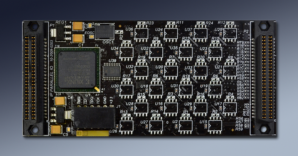
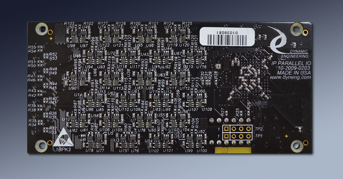
1.8x3.9 inches nominal single slot IP Module. Type II with low profile devices on rear. Suitable for PCIe, PCI, cPCI, VPX, VME, and PC104p stacks
IO
IP Module IO connector
Clocks
Compatible with 8 and 32 MHz IP bus operation. Oscillator position standard with 50 MHz. Custom frequencies can be accomodated.
IP Decoding
ID, IO, Mem and INT spaces supported.
Progammability
Each of the 4 pulse generators per IP module are programmable with period, pulse width, sense, interrupts, phase shift amount, and pulse count. Pulse count can be "free running" or a defined count.
IO Configuration
IO can be configured as single ended or dfferential pairs.
Interface
Open drain drivers or 40 MHz rated 485 transceivers. Mix and match on each IP Pulse Module.
Synchronization
Outputs can be synchronized to change together [across register boundaries]. Synchronization can be disabled.
Pull-up Resistor
470 standard, 1K, 4.7K available on TTL lines.
Interrupts
Master enable for data channels. Separate enable for each data channel. Interrupt at end of programmed operation or on each pulse. Status register with current interrupt request status. Interrupts are mapped to INTR0n on IP bus. Master enable can be disabled to allow polled operation.
Power Requirement
+5V. Approximately 52 mA at 5V typical unloaded.
SW Interface
All FPGA registers are read-write. All registers on word addresses.
Current Fab Number
10-2001-0103
Reliability
1.496 million hours GB 25C Bellcore MTBF
Custom
There is room in the FPGA for custom applications. Send in your specifications and we can quote a custom version for you
IP-Pulse Benefits
Speed
The IP interface supports 32 MHz operation for quick data loading and unloading. The interface supports interrupts and polling. Dynamic Engineering carriers support 64 bit[PCIe models]/32 bit[PCI models] to 16 bit conversion in HW allowing for higher throughput and lower overhead.
Price
System level cost is best when reasonably priced reliable hardware is used and NRE minimized. With IP-Pulse, driver support for the carrier and IP level, reference software, history of reliable operation, and fantastic client support your cost per unit and overall costs are attractive.
Ease of Use
IP-Pulse is easy to use. A simple register based interface to program the device(s). The User Application software and driver will get you up and running quickly. SIngle and multiple card capable. The driver has direct calls to program each of the ports. The example software includes loop-back testing. Interrupts are supported with the driver, and tested with the reference software. The driver and reference SW package supports API programming and includes a user interface to program pulse generation. The windows user interface provides a simple method to use IP-Pulse as a test asset without writing any software. Features like pressing a key to repeat the programmed pulse train are handy when debugging with a scope. All of the basic features contained in the API are supported. Please see the Hardware, Software, and Quick Start guide for the details.
Availability
IP-Pulse and standard IP Carriers are on our stocked items list. Even if temporarily out of stock with your model; our in-house manufacturing Dynamic Engineering can supply small and larger quantities in a short timeframe.
IP Specification Compatibility
IP-Pulse is compliant per the VITA 4 - 1995 specification. Tested with PCI and PCIe based carriers. All Dynamic Engineering IP Modules are compatible with the PCIe3IP, PCIe5IP, VPXI2IP, PCI3IP, PCI5IP, cPCI2IP, cPCI4IP, PC104pIP etc. IP-Pulse will operate with any IP specification compliant carrier board.
Part Number: IP-Pulse
Ordering Options
-
Replace the "IO" with the following options:
- -TTL 4 TTL Pulse Generators
- -422 4 RS-485 transceivers
- -XXX See Manuals section for customized versions and replace XXX with type
- -ROHS Use ROHS processing. Standard processing is "leaded"
- -CC Option to add Conformal Coating
Add additional options to the "- number"
IP-Pulse Drivers
Software Support for IP-Pulse includes: Windows® 7 and 10 compliant drivers
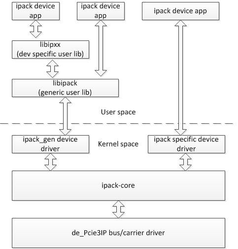
The IP driver is layered and operates on top of the Carrier driver. IP drivers are auto installed for each instance detected. Please see the Driver manuals for the specifics of each type.
Drivers and Reference SW are developed for each type / version of IP-Pulse implemented. When custom versions are ordered the NRE will include providing Windows, Linux, and or VxWorks packages. For off-the-shelf models, select on the manuals tab, the Windows® and Linux SW shown is included with your purchase of the HW. A small one-time charge is required for the VxWorks versions. Unsupported SW versions may have an NRE requirement.
Integration support is available. Please contact Dynamic Engineering for this option or download the Technical Support Description from the Company button.

Reference diagam of how our Linux Driver / Application layer operate with the Carrier and IP Module.
The IP driver is layered and operates on top of the Carrier driver. IP drivers are auto installed for each instance detected. Please see the Driver manuals for the specifics of each type.
Drivers and Reference SW are developed for each type / version of IP-Pulse implemented. When custom versions are ordered the NRE will include providing Windows, Linux, and or VxWorks packages. For off-the-shelf models, select on the manuals tab, the Windows® and Linux SW shown is included with your purchase of the HW. A small one-time charge is required for the VxWorks versions. Unsupported SW versions may have an NRE requirement.
Integration support is available. Please contact Dynamic Engineering for this option or download the Technical Support Description from the Company button.

Reference diagam of how our Linux Driver / Application layer operate with the Carrier and IP Module.
IP-Pulse Manuals
Click on the links to Download selected manuals in PDF format.
IP Carrier and Module Quick Start guide for Windows®7
IP Carrier and Module Quick Start guide for Windows®10
Currrent IP-Pulse Manual
IP-Pulse Win10 Driver Manual
IP-Pulse Win7 Driver Manual
IP-Pulse Quick Start Guide
VxWorks IP Module Manual
IP Carrier Linux Manual
Linux IP Module Manual
IP-Pulse Manual - original memory map and feature set PROM revision A updated 5/21/03
IP-Pulse XP Driver Manual


