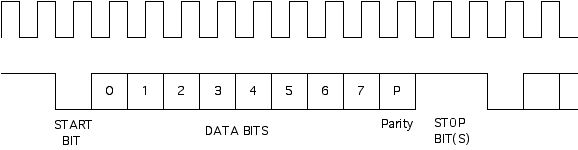
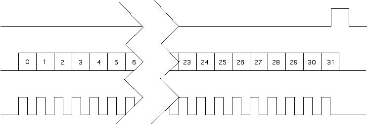
PMC-BiSerial-BA1 PMC Compatible Bus Data Analyzer with two protocols


The BA1 protocol implemented provides a Serial Data Analyzer function used for network snooping in a test environment. -32 FIFO option.
Please note that the PMC-BiSerial has been upgraded and the PMC-BiSerial-III is currently recommended for new designs

PMC-BiSerial is part of the PMC Module family of modular I/O components by Dynamic Engineering. The PMC-BiSerial is capable of providing multiple serial protocols. The PMC-BiSerial-BA1 implements two protocols. The first uses data and clock only, with start and stop bits delimiting eight data bits plus an odd parity bit. The second protocol uses a burst clock to shift in 32 bits of data. After the last clock a data sync pulse goes high for one bit period to indicate the end of the data word.

The PMC-BISERIAL-BA1 is designed to monitor traffic on two serial busses with different protocols. The first bus has a free running clock with a constant high level on the data line indicating an idle state. When the data line goes low this indicates the start of an eight-bit data transfer. After the start bit and the eight data bits, transferred least significant bit first, an odd parity bit is inserted followed by a high stop bit. The data line remains high until the next transfer begins.


PMC-BiSerial-BA1 Protocol #1


On the receive side, the data is latched on the rising edge of the clock, the parity is calculated and a bit is set in the stored data if an error is detected. An eight-bit field in the receive control register is used to determine the number of high bit-periods that must occur after the parity bit before it is assumed that the present data block i.e. message has ended. If this value is zero all data is treated as a single large block, if the value is one, a single stop bit is sufficient to indicate the end of a block, therefore every transfer is seen as a single byte block. If the value is between two and 255 that is the number of high bits that must be seen after the parity bit to cause the receiver to recognize the end of a block. When the end of a block is detected the byte count of that block is stored in the FIFO and when the next block begins a time stamp is stored. The first byte of a block is stored by itself in a 32-bit FIFO word. Subsequent data is stored up to three bytes per FIFO word.

The time stamp is generated by a 32- bit counter that counts microseconds derived from the on-board 10 MHz oscillator. This counter can be reset but otherwise counts continuously.

The second bus (see figure 3) transfers 32-bit values using a burst of 32 clock pulses. The data is also sent least significant bit first but is latched by the receiver on the falling edge of the clock. When the last clock pulse ends a one-bit wide sync is sent on a third serial line indicating the end of the word. The first word of a message has bits 31-24 high and this is used to determine the beginning and end of a message. When the first word is detected the count of the previous block is stored and the time stamp for the current block is latched and stored in the FIFO. The sync pulse causes the data word to be stored in the FIFO regardless of the number of clocks that occurred, however, if the clock count is not 32 an error bit is sent to the interrupt status register.


PMC-BiSerial-BA1 Protocol #1


Since the PMC-BISERIAL-BA1 is a bus monitor the transmit section is only used to simulate the bus data for test purposes. To simulate both protocols with a single transmit section an extra (33rd) bit has been added to the output data stream for each FIFO word. In the first protocol this bit provides the stop bit for the third data value in a 32-bit FIFO word. Each data word consists of a start bit eight data bits a parity bit and a stop bit for a total of 11 bits. The 33rd bit is always high and allows three 11-bit values to be sent from one FIFO word. In the second protocol this bit occurs between groups of 32 clock pulses and is therefore not registered as data.

Custom interfaces are available. We will redesign the state machines and create a custom interface protocol. That protocol will then be offered as a standard special order product. Please see our web page for current protocols offered. Please contact Dynamic Engineering with your custom application.


If your situation demands a custom application then we will update the Xilinx FPGA. Send us your timing and we will send you the interface....
email us your wish list or call today!


Related Products:
68 position terminal strip to SCSI III connector adapter and BiSerial compatible SCSI III cable

PMC-BIS-Eng-Kit..........Engineering Kit for PMC-BiSerial includes Board level Schematics [PDF], Reference Software [WIN NT, WinRT, Visual C ZIP file], HDEterm68-MP, HDEcabl68


You must have Adobe Acrobat to read our PDF files.

PMC-BiSerial-BA1 manual PDF.


Custom, IP, PMC, PC*MIP, PCI, VME Hardware, Software designed to your requirements


Home | News | Search the Dynamic Engineering Site


[an error occurred while processing this directive]