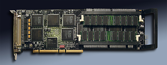
PCI-LVDS-8T is a PCI card with 8 channels. Each channel has memory, processing, and LVDS serialized output. The output is compatible with the TIA/EIA-644 LVDS standard. The serialized bit stream is transmitted with parallel serial data streams plus a reference clock. With the LVDS electrical standard long distances and quiet operation at high rates are possible. The TI interface device accepts a parallel word, and reference clock and outputs the seralized LVDS signals. The parallel word can be up to 21 bits. Each group of 7 bits are serialized independently using the common reference clock and upconverted to the LVDS transmit clock at 7X the parallel rate. The base model "8T" uses 14 of the 21 bits for the data and control. The "2T" model uses all 21 bits of the parallel interface.
The 8 channels are programmable with the ability to enable the channels of interest, the size of the memory allocated to each channel, the method of transmission and the synchronization of each transmission. Each channel is supported with independent FIFO memory at strategic locations to allow full speed operation and the use of the banked SDRAM.
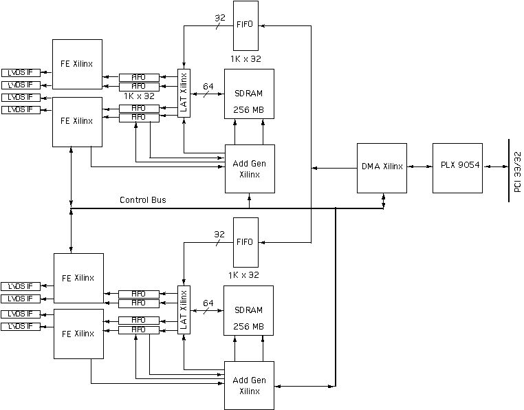
The data to be transmitted is loaded into the SDRAM using DMA transfers. Once the memory is loaded the hardware is programmed for type of transmission. Looping with repeated data, single pass, and combinations are possible. For example a preamble can be sent once, then loop through the body of data a programmable number of times, and then a post amble can be sent. Standard single pass data can also be sent. The SDRAM is in two blocks. Each block is assocated with 4 channels. The start address for each channel can be programmed as well as the length of the data to be sent allowing all of the memory to be allocated to once channel or one quarter to each channel or whatever is required. For example in the "2T" model all of the memory for each bank is allocated to a single channel in each bank. In standard "8T" operation the channels are set-up in a symmetrical fashion.
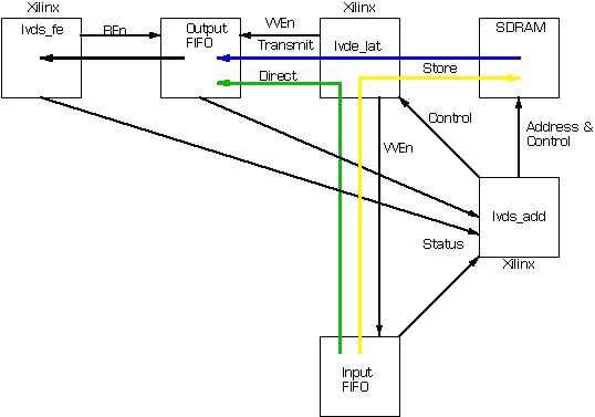
Data is read from the memory and loaded into the FIFO associated with that channel. The Latch Xlinx converts from 64 bit SDRAM data down to 32 bit FIFO and upconverts the reference rate to keep the pipeline balanced. Data is moved in Bursts whenever there is enough to move a complete page. Any LW coherent size can be moved with the hardware automatically making the necessary paging adjustments.
Once in the FIFO the transmission section can read the data and format for moving to the Serializers. In the case of the "8T" the data width is reduced, and tags inserted to control the flow. In the "2T" the processing is different as all 21 bits of the serializers are used. The upper bits are used for flow control within the "2T" and stripped off prior to transmission. The final stage is preloaded when the channels are enabled locally.
If programmed to use an external trigger the hardware will then wait for that trigger event before starting to send the programmed sequence of data. External clocks and triggers can be used and the "8T" design supports retransmission of the clock and trigger to allow multiple boards to be controlled in a daisy chain fashion. The clock and trigger are accepted at the front panel and retransmitted at the rear to allow for internal chassis wiring. When the external trigger is not used the channels can still be started coherently via software with the master strart bit.
The first customers for the 8R and 8T needed to use multiple cards within each chassis. Specifically 10 cards were placed into an expansion chassis providing 80 channels. The power consumption is not particularly high, and with 10 cards was too much for the 5V or the 3.3V rail of the power supply. The cards come with an option to operate using the 5V or the 3.3V power rail as the main source of power to allow multple boards to be used in the same chassis without overloading the power supply - it is recommended that you mix 5V and 3.3V cards when working with multiple cards. Please note that the PCi interface is "universal voltage", and not affected by the power rail option.
For more complete information please download the hardware manuals. Bit maps, diagrams, pinouts etc. are contained within.