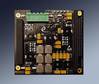
PC104pPWR12
12V based Power Supply
PCI-104. PC104p, and PC104 Stacks


PC104pPWR12 power supply provides for the +5V, +3.3V, +12V, minus 12V and minus 5V from a 12V supply, battery etc. Each rail is protected with "self-healing" fuses. The supply uses switching technology to provide high efficiency coupled with low pass filtering to provide low noise and fast response to transient loads. The handy locking screw terminal style connector allows discrete wiring solutions within the chassis. The mating connector and 12" cable are included with the PC104pPWR series. PC104pPWR12 is intended to work with a 12V input. For 28V applications please see PC104pPWR28.

Vehicles and other systems use 12V power to operate equipment. PC104pPWR12 is designed to operate from a 12V source.

Power is routed from the power supplies to connectors with mini-planes each of which is rated for more than the maximum draw. The total power dissipation is limited to the external power supply capabilities. Each rail can draw to the maximum to cover situations where the power utilization is not balanced. 10A max current on 5V, 10A max current on 3.3V, 4A max current on -12, 4A from +12V, 4A max on minus 5V. The VIO is selected from the 3.3 or 5V supply and is included in the 10A available on those rails. Please note that special builds can be done to remove unused power supplies for your production requirements. Please also note that the +/- 12V and -5V supplies are limited by a single pin on each connector for those voltages per the specification. The stack pins can handle slightly more than 1A under most conditions.

The maximum rating is based on room temperature. The power supply components are all rated for 85C or higher ambient temperature. The fuses in particular have a curve which derates over temperature. At 23C the fuses "hold" rating is set to handle the maximum designed draw. For example 10A on 5V rail. At 60C the fuse hold figure derates from 2.5 to 1.65 leading to a potential max current of 6.7A at 5V at an ambient of 60C. [1.65 *2 fuses * 12V * .85 / 5]. In practice the hold is the guaranteed current that will pass at a given temperature and the trip is the guaranteed trip current at a given temperature. Somewhere between the hold and the trip is the point where the fuse will actually trip. This means, in most cases with the trip 2x the hold, the power supply will continue to deliver full power up through 60C ambient, but can´t be guaranteed beyond the hold value. Also the efficiency number of 85% is very conservative and it is more likely that 90+% would be achieved at full load which will also increase the available current.

The 12V supply is designed to source uo to 18A = 216 Watts. At max theoretical load 199 W are sourced by the secondary supplies. In reality the 12V, -12V, and -5V circuits will not be loaded to 4A since the PC104p stacking pins can't handle that much current. The 12V power supply will run at something closer to 50% providing plenty of margin over temperature.

The +12V rail is powered up first since that is the reference, followed by the -12V and -5V power rails and finally the 3.3 and 5V power rail. The rails are delayed relative to one another to reduce the inrush current requirement. The 12V rail is used to power the -12V and -5V rails leading to a delay based on the rise time of the 12V and inherent delay of the downstream supplies. The 5V and 3.3V supplies have a voltage supervisor circuit triggered from the 12V to delay the start-up of these supplies by several mS.

The reference voltage is connected to the power supply through a right angle connector. PC104pPWR12 has a right angle board mount connector. The cable side is also right angle for convenient cable routing in your chassis. Two 12V, and two ground pins are used to allow for a flexible cable internal to the PC104 chassis. Each pin can handle 20A providing a 100% safety margin.

The mating connector and a 12" long 20 AWG cable are included with the PC104pPWR12 for easy connection to your power connector. Please contact us for longer or shorter wire lengths or termination to the power connector of your choice.

LED´s are provided on the 3.3, 5V, +12V, -12V and -5V rails for an easy visual check.

PCI VIO is programmable allowing 5V or 3.3V PC104p cards to be used. Many PC104p and PCI-104 cards are "universal" and can work with 3.3 or 5V PCI definitions. A shunt is provided for the user to select 5V or 3V operation. The shunt or open definitions are in the silk-screen for easy reference.

For chassis with Fans installed the PC104pPWR12 has 4 fan power positions available to provide an easy to connect to source for the fans. The 2 pin headers or direct wire connections can be made to the fans; it is envisioned that the rear surface of the power supply would be used to provide a direct path to the fans. You have a choice of 5V or 12V power for the Fans. The power is fuse protected with a total of 2A across the 4 connectors. The power is included in the 5V or 12V power budget. Please note PC104p-Chassis has an air-cooled option that is designed to work with the fan power option.

For conduction cooled situations PC104pPWR12 is designed with heavy copper planes to both distribute the power and to distribute the heat. The 4 mounting positions are tied directly to the (2) 4 oz ground planes for good thermal contact. The PC104p-Chassis is designed to use the mounting hardware to route the thermal load to the end plates and then to the chassis wall via thermally conductive vibration damping springs.

Power capabilities and requirements are determined by the client´s situation. PC104pPWR12 can supply the maximum power on each rail as specified above with certain limitations. Please see the manual for a more complete discussion. The basics are that the input power must exceed the output power plus the power consumed by the power supply. The "Power12" design is very efficient with better than 90% efficiency at most loads. For example with 8A on the 5V rail 40W of output power are desired. 40/.9 = 44.44 W input power required. WIth a 12V input, 3.7A would be required. The input current should be calculated based on the required output power consumed and reference voltage. The 12V input current is limited to 18A max. 3.7A is well under the limit for the 12V. Please note that the 12V rail has no conversions in the path.

Please also note that voltages greater or less than 12V can be used with the consequence that the +12V supply will not be at +12V. At lower input voltages the secondary supplies will require more input current to create the same output current. The supervisor circuit on the +5 and +3.3 supplies triggers at approximately 10.37V which will limit the lower input voltage. If you require a lower input voltage we can modify the voltage detector settings to accommodate as long as the supply has adequate current and does not exceed the "12V" rail current. On the high side please note that there are 25 and 50V rated bulk capacitors. For voltages much above 12V the 25V tantulums will need to be replaced with 50V ceramics which will reduce the total capacitance and increase the ripple in the supply. Please contact engineering@dyneng.com to make these adjustments and to generate a part number for your application.

Testing:
Extensive load testing has been done both on the bench and in the PC104p-Chassis.
Please note: The following test data was recorded from tests using the PC104pPWR28 version of the board. The same PCB is used for both the PC104pPWR28 and PC104pPWR12.

2 hours at each load with temperature at FET´s, 5V, 3V, +12, -12, and -5V measured and recorded plus current from 28V supply and room temperature. Loads in 1A steps. Tested with closed short chassis no fans [other than on load boards], closed chassis with internal circulation fans, and air cooled chassis configurations. All testing performed on bench top at room temperature with minimal [if any] air flow unless noted, and little conduction to bench [standard ESD bench top tends to be a pretty good insulator] Revision A boards with modifications to allow for up to 9.5A on 5V and 3.3V rails. With Revision C boards new FET´s with "PowerPak" footprints are incorporated along with other layout changes which will enhance the load limits under all conditions.

In a fan-less still air situation using a sealed 7 slot version of PC104p-Chassis approximately 40W can be supplied [to the load] maximum continuous at room temperature. With external air blowing across chassis an additional 15-20C is achieved.

With the addition of an internal fan board [2 x 40 mm 12V fans(2)] and sealed 11 slot chassis, in still air, a maximum of 64W is achieved. 12V(.22A), 5V(7.4A), 3.3V(2.2A), -5V(1A), -12V(1A). Please note that the chassis is hot to the touch in this configuration. With External air flow the internal temperature at the hottest component shifts from 74C to 55C - simple blow across the box test. Please note: Industrial temperature parts with an ambient of 85C or higher are standard. Measuring at the surface of the FET provides a very conservative limit.

In the air-cooled configuration: 11 slot chassis, dual 12V fans mounted at chassis rear plate, dual openings at front plate the loading can be increased. 12(.22A), 5(9.4A), 3.3(7.7A), -5(1A), -12V(2A). [104W] At 25C room temperature, Hottest part was 66C. Max rated is 85C air temp - using for conservative component temperature leaves ~20C margin or an operating range of up to 40C or so at this load level. The 12V supply can handle more than 1A, but we only loaded with the two fans. PC104p-COOL can be added to the stack to provide fan based cooling. The COOL card has "Zero Slot" technology to allow direct insertion without adding requirements for additional spacers etc.


Revisions:
Rev A : Initial design with SO8 pkg FET´s 5V & 3.3V @4A std.
Rev B : update for 5V & 3.3V @8A std.
Rev A : Combined with PC104pPWR28 on new PCB PC104pPWR. Switched to PowerPak FET´s, larger inductors, moved fuses ahead of supplies etc. 10A on 5V and 3.3V std. [Rev C is RevA on new Fab]

If you have custom requirements please call or e-mail us with the details.

PC104pPWR12 Features

  • Size
  • Standard PCI-104. PC104p, PC104

  • Voltages Supplied
  • +5, +3.3, +12, -12V -5V, and VIO

  • VIO
  • VIO is programmable by the user via shunt to 5V or 3.3V.

  • Protection
  • Self Healing fuses on each rail, over-voltage protection

  • Indicators
  • LED´s are provided on each power rail 3.3V, 5V, 12V, M12V, M5V

  • Cabling
  • Pre-wired mate to PC104pPWR12 is available for ease of connection within your system.

  • Thermal
  • The PC104pPWR12 is based on switching power supplies for minimal heat dissipation and maximum power transfer to the PCI-104, PC104p or PC104 stack. Efficiency is a function of load. In many cases no cooling will be required, in high load, and high temperature or high altitude systems cooling requirements should be considered. The PC104pFAN board can provide forced air cooling for the PC104 stack. The PC104pPWR12 has heavy internal planes - 4oz copper to handle the current and spread the heat. The ground planes are tied to the PC104 mounting holes to make use of the PC104 stack for cooling to the external chassis wall. The PC104p Chassis is designed to transfer heat in the PC104 spacers to the end plates of the chassis.


    PC104pPWR12 Benefits

  • Power
  • Energize all of the rails in your design with a single power supply.

  • Price
  • The PC104pPWR12 is cost effective, and ready to use. Just plug in and attach the supplied cable. Low system cost due to easy installation, easy to achieve cooling requirements, and reliability keep your installed price low. Quantity discounts are available.

  • Warranty
  • 1 year warranty

  • Ease of Use
  • The PC104pPWR12 is easy to use. A Plug and Use interface to the PCI-104, PC104p or PC104 stack.

  • Availability
  • We work to keep the PC104pPWR12 in stock. Send in your order and in most cases have your hardware the next day - delivered to you via FedEx.

  • Size
  • Complies with standard PCI-104, PC104p and PC104 dimensions

  • Compatibility
  • The PC104pPWR12 is PCI-104, PC104p and PC104 compliant per the specification. All Dynamic Engineering PC104p Modules are compatible with the PC104pPWR12.


    Ordering Information
  • PC104pPWR12: Standard PC104pPWR12 with both PCI and ISA connector and all of the power supply rails populated. Includes internal Power Cable with Board side mate. 12" long. Standard leaded solder used.
  • -ROHS: change to ROHS processing.
  • -NM5 delete minus 5V capability
  • -PCI delete PC104 connector leaving only PCI side connector, also removes Minus 5V supply
  • -ISA delete PCI connector leaving only PC104 side connector, also removes 3.3V supply
  • -FAN add headers to support fans. FAN5 = 5V, FAN12 = 12V, add RA for right angle header, add R for rear mount. -FAN12RAR is 12V fused power on rear mounted right angle headers. There are 4 headers. 2A fused power [total] across headers.
  • -CC add conformal coating to board.


    Board Options


    Manual
    You must have Adobe Acrobat to read our PDF files.

    Download the
    PC104pPWR12 Manual in PDF format.


    Custom, IP, PMC, PC*MIP, PCI, VME Hardware, Software designed to your requirements


    Home | News | Search the Dynamic Engineering Site